| Author |
Message |
alanwilder81
Joined: Sep 03, 2016
Posts: 310
Location: italy
|
 Posted: Sat Sep 03, 2016 2:49 pm Post subject:
Yves' archive, "Synthesizer schematics" by Thierry Rochebois Posted: Sat Sep 03, 2016 2:49 pm Post subject:
Yves' archive, "Synthesizer schematics" by Thierry Rochebois |
  |
|
hello everyone,
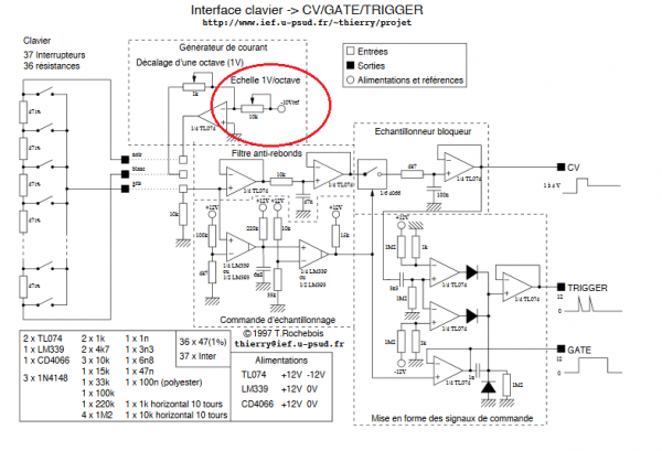
has anybody attempted to build the "keyboard interface CV-GATE-TRIGGER" circuit?
it looks really nice and low components count.
It is in Yves's archive, on the last article on the page bottom, called "synthesizer schematics" by Thierry Rochebois
http://yusynth.net/index_en.php?&arg=1
any comment or help would be appreciated |
|
|
Back to top
|
|
 |
yusynth

Joined: Nov 24, 2005
Posts: 1314
Location: France
|
| Posted: Tue Sep 06, 2016 1:23 am Post subject:
|
|
|
Hi
No I haven't built it, but it was a student project that was successfully completed and the schematics published by Thierry were all tested therefore I guess you may be pretty confident in these. I see no flaw in them.
_________________
Yves |
|
|
Back to top
|
|
|
alanwilder81
Joined: Sep 03, 2016
Posts: 310
Location: italy
|
| Posted: Tue Sep 06, 2016 1:48 am Post subject:
|
|
|
good morning Mr. Yves,
greetings from Italy.
I'd like to show you my greatest appreciation for your amazing works and your efforts in sharing accurate schematics and knowledge with all of us.
That enabled me to build some of your modules,in particular the Steiner filter and the saw core VCO that proved excellent.
i am now building the "simple VCA" and the "classic ADSR", in order to make a very simple architecture synth.
I can now confidently build the keyboard circuit as soon as i get the missing components, and i will let you know about the developements.
Again, thanks for your time, and i hope i can get some of your advices when getting the modules together.  |
|
|
Back to top
|
|
|
alanwilder81
Joined: Sep 03, 2016
Posts: 310
Location: italy
|
| Posted: Sat Sep 10, 2016 5:23 am Post subject:
|
|
|
hi Yves,
I built the VCA module, listed on "my old synths" circuit collection, from US1.
here's the link
http://yusynth.net/gear/US1/images/VCA-US1.gif
can i use it as a simple VCA for my mono synth project? How do i go about setting the trimmers properly?
I'd like to know how it compares to the more advanced "simple VCA", which i can't build, as i haven't got a dual trace scope 
thanks in advance !  |
|
|
Back to top
|
|
|
gdavis
Joined: Feb 27, 2013
Posts: 359
Location: San Diego
Audio files: 1
|
| Posted: Sun Sep 18, 2016 1:22 am Post subject:
|
|
|
| alanwilder81 wrote: | hi Yves,
I built the VCA module, listed on "my old synths" circuit collection, from US1.
here's the link
http://yusynth.net/gear/US1/images/VCA-US1.gif
can i use it as a simple VCA for my mono synth project? How do i go about setting the trimmers properly?
I'd like to know how it compares to the more advanced "simple VCA", which i can't build, as i haven't got a dual trace scope
thanks in advance ! |
The US1 circuit only works as an AC (audio) VCA. The "simple VCA" can work as AC or DC (for control voltages). It adds a trimmer to null the DC offset (not important for AC) and some control knobs to give it more flexibility. If you just want a basic VCA for the audio output of your synth, US1 should be fine.
Setting the trimmers for the US1 is actually very similar to trimming the "simple VCA" and using a dual trace scope would be ideal. The idea is to match the output signal to the input signal. However, in a pinch you can do it with a single trace scope, just measure the input waveform then adjust the trimmers while observing the output until it's the same as the input. If you don't have a scope, just set the balance trimmer in the middle and the gain trimmer by ear. Won't be perfect but if it sounds OK then it's OK.
_________________
My synth build blog: http://gndsynth.blogspot.com/ |
|
|
Back to top
|
|
|
alanwilder81
Joined: Sep 03, 2016
Posts: 310
Location: italy
|
| Posted: Sun Sep 18, 2016 4:44 am Post subject:
|
|
|
hey gdavis,
thanks for replying 
it's the first time i've really ventured on building a VCA,so please don mind some noob questions ! 
can you shed some light on the basic VCA knobs and parameters ? am bit confuse as to what each knob does what. You know.
As far as what i can grasp, a VCA input can be both for AC and DC,respectively for processing audio stuff and CV signals. Right?
Now,i am only interested in running my humble VCO through the VCA to get a volume envelope.
Then, is the DC offset knob irrelevant to do my job?
Else,i keep seeing the BIAS knobs. What are they? And the gain knob?
When i built the US1 VCA i noticed that the volume stayed always ON, there was no way to silence it.
Is that how it's supposed to work?
excuse my many questions.trouble is ,despite much researching they have remained unanswered for most part.
thanks in advance !! |
|
|
Back to top
|
|
|
gdavis
Joined: Feb 27, 2013
Posts: 359
Location: San Diego
Audio files: 1
|
| Posted: Sun Sep 18, 2016 2:03 pm Post subject:
|
|
|
| alanwilder81 wrote: | hey gdavis,
thanks for replying
it's the first time i've really ventured on building a VCA,so please don mind some noob questions !
can you shed some light on the basic VCA knobs and parameters ? am bit confuse as to what each knob does what. You know. |
Input Level #1: Controls the level of the signal coming into input 1. Kind of like a volume control for the input. Can be useful if the signal coming in is too strong and causing the VCA to distort for example.
Gain: Kinda of like a manual control for the VCA, lets you adjust the output volume without a control input or shift the overall effect of the control input louder or quieter.
Control Level #1: Controls the amount of effect from the signal on control input 1. For example, if you have a 0-10V CV coming in, the knob can reduce the range so that the VCA only opens and closes a little bit instead of full volume.
Gain and Control Level together give you flexibility that can be very useful when using the VCA with CV signals, but aren't as useful for audio IMO. Much easier to understand when you can actually try them out.
| Quote: | | As far as what i can grasp, a VCA input can be both for AC and DC,respectively for processing audio stuff and CV signals. Right? |
In general that is correct. Be aware that for the "simple VCA", you need to remove C3 and C4 in order for it to work as a DC VCA. The US1 VCA lacks the offset trimmer making it less desirable for CV even if the input cap were removed. You can't use coupling caps with DC because the cap blocks DC and only passes signals above a certain frequency.
| Quote: | Now,i am only interested in running my humble VCO through the VCA to get a volume envelope.
Then, is the DC offset knob irrelevant to do my job? |
That is correct. Whatever audio input you connect the output of the VCA to is going to have a coupling cap that will remove any DC offset. You can't hear DC offset, it's only a problem with audio if it's so large that the signal clips, but that's why the coupling caps are there, to prevent that from happening. For CV's, especially pitch CV, small DC offsets can be very noticeable which is why you have a trimmer for it in DC VCA's.
| Quote: | | Else,i keep seeing the BIAS knobs. What are they? And the gain knob? |
Not sure what you're referring to as bias. Gain is described above, basically a manual control for opening and closing the VCA.
| Quote: | When i built the US1 VCA i noticed that the volume stayed always ON, there was no way to silence it.
Is that how it's supposed to work? |
No, it should be silent when the CV input is 0V. The 22k trimmer needs to be adjusted so it's just silent. Then, increasing the CV input up to 10V should cause the VCA to open up proportionally.
| Quote: | excuse my many questions.trouble is ,despite much researching they have remained unanswered for most part.
thanks in advance !! |
No problem, hope that helped. Like I said, it's difficult to understand just reading about it. Really helps if you have a working synth to play with to understand what this stuff does. You might want to look for a free VST pluggin or something to try out and get a better understanding of how it should work.
_________________
My synth build blog: http://gndsynth.blogspot.com/ |
|
|
Back to top
|
|
|
alanwilder81
Joined: Sep 03, 2016
Posts: 310
Location: italy
|
| Posted: Sun Sep 18, 2016 2:44 pm Post subject:
|
|
|
hello gdavis,
many thanks for your incredibly articulate response. I'll take a deeper look later.That sheds a light on the VCA working principles great stuff.
I have played VST synths forever. I've learned the crap out subtractive synthesis right on those fake sounding emulation 
As bad,as cold, as sterile VST's might sound, they gave me the opportunity to get a solid gasp of the audio path,at least.
Also ,i recently had the chance to play some real analog baby, and i was hooked. I decided it was time to go DIY all the way because it's the real sound that i am after.
So i am humbly trying to get grasp with basic VCO-VCF-VCA architecture mono synths.Very rewarding experience ! |
|
|
Back to top
|
|
|
alanwilder81
Joined: Sep 03, 2016
Posts: 310
Location: italy
|
| Posted: Sun Sep 18, 2016 3:09 pm Post subject:
|
|
|
to gdavis,
should you need me to provide you with the schematics ive been working on,just dont hesitate to ask . I'll keep you posted with the next VCA developments. Again, thanks for the great infos and willingness ! |
|
|
Back to top
|
|
|
alanwilder81
Joined: Sep 03, 2016
Posts: 310
Location: italy
|
| Posted: Tue Sep 20, 2016 10:32 am Post subject:
|
|
|
hey Gdavis,
there's some great news
i finally unraveled the VCA mistery,after making the US1 VCA and another one from EFM website by fonitronik.
The knobs are starting to make sense now, i manage to modulate the VCA by using the US1 AR generator.
Plus, i found a nice VCA ,very similar to Yusynth one,just a semplified version of the "simple VCA" that is in turn carbon copy of the US1 vca i built.
here's the schematics. It works,for whoever would be interested in it
http://kassu2000.blogspot.it/2015/10/vca.html  |
|
|
Back to top
|
|
|
Cfish

Joined: Feb 24, 2016
Posts: 477
Location: Indiana
|
| Posted: Wed Sep 21, 2016 6:48 pm Post subject:
|
|
|
The simplest example of this type of VCA I have ever found is the early PAIA VCA schematics. Sorry I looked for a few and couldn't find a link to it, but I know it's on line.
Glad to hear your making progress alanwilder81 |
|
|
Back to top
|
|
|
alanwilder81
Joined: Sep 03, 2016
Posts: 310
Location: italy
|
|
|
Back to top
|
|
|
yusynth
Joined: Nov 24, 2005
Posts: 1314
Location: France
|
| Posted: Tue Oct 25, 2016 10:19 am Post subject:
|
|
|
Yes you can
_________________
Yves |
|
|
Back to top
|
|
|
Cfish
Joined: Feb 24, 2016
Posts: 477
Location: Indiana
|
| Posted: Thu Oct 27, 2016 3:25 am Post subject:
|
|
|
Hi alanwildr81
I have had this in my list of circuits to try since you posted it.
Would love to hear how it turns out for you. Looks like it should work great.
Wish I had seen the schematic a couple of years ago, however if I had, I might not have learned what I learned trying to build one I could understand. |
|
|
Back to top
|
|
|
alanwilder81
Joined: Sep 03, 2016
Posts: 310
Location: italy
|
| Posted: Fri Oct 28, 2016 11:38 am Post subject:
|
|
|
thanks very much Yves !
another question.
on the far left of the schematics,I see three outputs from the keyboard circuit called, from top to bottom, "noir", "blanc" ,"gris" .
They are connected to the circuit by the means of "dotted lines". Are those lines to be considered as regular cables and connections?
is there any particular reason for them not to be drawn as the rest of the circuit connectionss?
thanks ! |
|
|
Back to top
|
|
|
alanwilder81
Joined: Sep 03, 2016
Posts: 310
Location: italy
|
| Posted: Fri Oct 28, 2016 11:45 am Post subject:
|
|
|
to Cfish
I am glad you found inspiration from that schematic.i am just about to breadboard it. |
|
|
Back to top
|
|
|
yusynth
Joined: Nov 24, 2005
Posts: 1314
Location: France
|
| Posted: Sat Oct 29, 2016 12:39 am Post subject:
|
|
|
| alanwilder81 wrote: | thanks very much Yves !
another question.
on the far left of the schematics,I see three outputs from the keyboard circuit called, from top to bottom, "noir", "blanc" ,"gris" .
They are connected to the circuit by the means of "dotted lines". Are those lines to be considered as regular cables and connections?
is there any particular reason for them not to be drawn as the rest of the circuit connectionss?
thanks ! |
Yes they are connected. I suppose the dotted lines symbolise a ribbon cable with connectors on each side that interconnect the circuit board to the keybed board.
_________________
Yves |
|
|
Back to top
|
|
|
indigoid
Joined: Apr 20, 2016
Posts: 5
Location: Sydney, Australia
|
| Posted: Fri Nov 04, 2016 5:52 am Post subject:
|
|
|
so I built myself a US-1 VCA also. My system is Eurorack, so +/-12V. I used TL072 and 2n3904 since that's what I had at hand, and as people often say 2n3904s are usually quite well matched for Vbe if they're from the same strip of paper tape, I didn't bother matching them.
When feeding it relatively-fast-but-not-audio-rate signals the top half [only] of the output wave is notably rounded off, as if it had been slewed.
Transistors not sufficiently matched?
I will keep tinkering with it. |
|
|
Back to top
|
|
|
yusynth
Joined: Nov 24, 2005
Posts: 1314
Location: France
|
| Posted: Fri Nov 04, 2016 6:27 am Post subject:
|
|
|
Yes probably
_________________
Yves |
|
|
Back to top
|
|
|
alanwilder81
Joined: Sep 03, 2016
Posts: 310
Location: italy
|
| Posted: Tue Nov 08, 2016 12:16 pm Post subject:
|
|
|
| thanks Yves,now it makes more sense ! |
|
|
Back to top
|
|
|
alanwilder81
Joined: Sep 03, 2016
Posts: 310
Location: italy
|
| Posted: Wed Nov 16, 2016 5:19 pm Post subject:
|
|
|
hello Yves,
i finally managed to build the keyboard circuit published by Thierry Rochebois.
It looks it works, i am immensely happy with that.
I would like to thank you for this and share this success, my synth now is complete |
|
|
Back to top
|
|
|
yusynth
Joined: Nov 24, 2005
Posts: 1314
Location: France
|
| Posted: Thu Nov 17, 2016 12:56 am Post subject:
|
|
|
Excellent
_________________
Yves |
|
|
Back to top
|
|
|
alanwilder81
Joined: Sep 03, 2016
Posts: 310
Location: italy
|
|
|
Back to top
|
|
|
yusynth
Joined: Nov 24, 2005
Posts: 1314
Location: France
|
| Posted: Fri Nov 18, 2016 10:25 am Post subject:
|
|
|
Or you can use a resistor, a 10V zener and a capacitor to create the 10V reference
_________________
Yves |
|
|
Back to top
|
|
|
alanwilder81
Joined: Sep 03, 2016
Posts: 310
Location: italy
|
| Posted: Fri Nov 18, 2016 10:30 am Post subject:
|
|
|
| thanks Yves ! |
|
|
Back to top
|
|
|
|

 Forum index » DIY Hardware and Software » YuSynth