| Author |
Message |
dioioib

Joined: May 23, 2008
Posts: 56
Location: canada
|
 Posted: Fri May 23, 2008 3:55 pm Post subject:
Ring Modulator Posted: Fri May 23, 2008 3:55 pm Post subject:
Ring Modulator
Subject description: DIY Ring Modulator |
  |
|
Hello everyone,
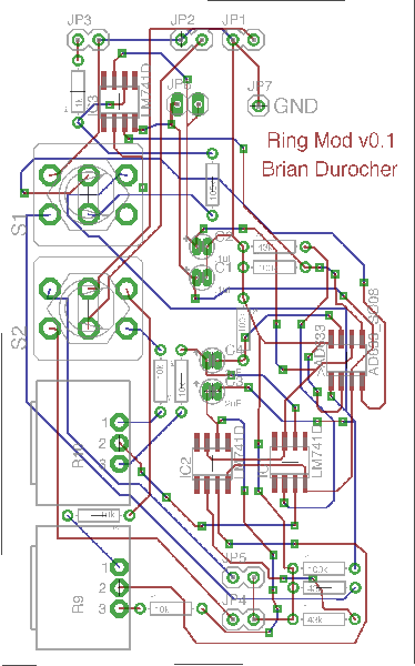
I have been working on a ring modulator with preamp / distortion and bypass switches I will post the schematic and the board layout for you. However, I have run into an issue. Currently I am running off dual 9v +/- batteries, I am able to get a faint sound through the FX board but nothing usable. I am working on a +/- 12v supply as well. Is my problem caused by a lack of power? Have a look and let me know if you can see any glaringly obvious errors.
| Description: |
|
| Filesize: |
88.64 KB |
| Viewed: |
562 Time(s) |
| This image has been reduced to fit the page. Click on it to enlarge. |
|
| Description: |
|

Download (listen) |
| Filename: |
v01_ringmodulator.pdf |
| Filesize: |
1.49 MB |
| Downloaded: |
547 Time(s) |
|
|
|
Back to top
|
|
 |
blue hell
Site Admin

Joined: Apr 03, 2004
Posts: 24423
Location: The Netherlands, Enschede
Audio files: 297
G2 patch files: 320
|
Posted: Fri May 23, 2008 4:05 pm Post subject:
Re: Ring Modulator
Subject description: DIY Ring Modulator |
|
|

| dioioib wrote: | | glaringly obvious errors. |
The polarity of C1 ... but that's not causing the problem 
Maybe you need more amplification around IC3 (as U$1 does a /10) ?
_________________
Jan
also .. could someone please turn down the thermostat a bit.
 |
|
|
Back to top
|
|
|
Inventor
Stream Operator

Joined: Oct 13, 2007
Posts: 6221
Location: near Austin, Tx, USA
Audio files: 267
|
| Posted: Sat May 24, 2008 12:25 am Post subject:
|
|
|
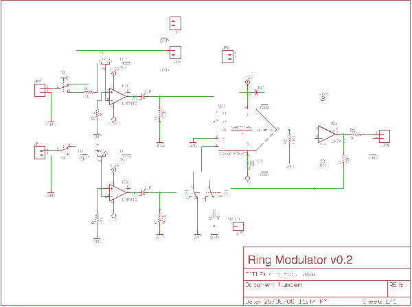
Yes, your 741 opamp input pins are connected backward on the two input buffers. You need negative feedback for an inverting amplifier stage, not positive feedback. Running an opamp with positive feedback is in general not recommended unless you purposely want the opamp's output to swing from rail to rail for some reason, such as in a relaxation oscillator (ahhhh, how relaxing). Try lifting the 741 input pins and soldering little bitty wires to swap the inputs. You can debug this with a meter (if you don't have a scope) by measuring the AC RMS value of the input and the output. There should be signal at both the input and the output when the circuit is working properly. Good luck and remember: opamps *like* negative feedback, it keeps them stable!
_________________
"Let's make noise for peace." - Kijjaz |
|
|
Back to top
|
|
|
dioioib
Joined: May 23, 2008
Posts: 56
Location: canada
|
| Posted: Sun May 25, 2008 8:42 pm Post subject:
|
|
|
So swap pins 2 and 3 of each input op amp and fix the reversed cap and I should be good to go?
As for the green wiring you should see my prototype. 
I'll post the results when I am finished. |
|
|
Back to top
|
|
|
dioioib
Joined: May 23, 2008
Posts: 56
Location: canada
|
Posted: Sun May 25, 2008 8:59 pm Post subject:
Subject description: v0.2 |
|
|
Here is an update to the schematic and board. I will try cutting the traces and green-wiring my prototype tomorrow.
| Description: |
|
| Filesize: |
173.87 KB |
| Viewed: |
651 Time(s) |
| This image has been reduced to fit the page. Click on it to enlarge. |
|
| Description: |
|
| Filesize: |
223.17 KB |
| Viewed: |
567 Time(s) |
| This image has been reduced to fit the page. Click on it to enlarge. |

|
|
|
|
Back to top
|
|
|
Inventor
Stream Operator
Joined: Oct 13, 2007
Posts: 6221
Location: near Austin, Tx, USA
Audio files: 267
|
| Posted: Mon May 26, 2008 1:41 pm Post subject:
|
|
|
Yeah, you should be good to go after that, just let us know how it works.
_________________
"Let's make noise for peace." - Kijjaz |
|
|
Back to top
|
|
|
dioioib
Joined: May 23, 2008
Posts: 56
Location: canada
|
Posted: Tue May 27, 2008 5:41 pm Post subject:
Ring Mod
Subject description: Ring Mod |
|
|
Not so hot I think I blew something.. It might have been a cap, all I know is there was smoke. 
Any Suggestions ? |
|
|
Back to top
|
|
|
blue hell
Site Admin
Joined: Apr 03, 2004
Posts: 24423
Location: The Netherlands, Enschede
Audio files: 297
G2 patch files: 320
|
| Posted: Tue May 27, 2008 5:55 pm Post subject:
|
|
|
& the circuit works not?
Most times visual inspection will show where the smoke came from, when it was on the underside of a component it could be hard, maye some smoke residue on the PCB ...
_________________
Jan
also .. could someone please turn down the thermostat a bit.
|
|
|
Back to top
|
|
|
dioioib
Joined: May 23, 2008
Posts: 56
Location: canada
|
| Posted: Tue May 27, 2008 6:28 pm Post subject:
RingMOD |
|
|
| There is nothing visible but I can smell some char comming from the 2.2uF decoupling caps C3 C4. But they are rated to 100v so that doesn't make any sense when running off 9v unless my input audio voltage was too high. I was only running a Virus TI through it to test though nothing too crazy. |
|
|
Back to top
|
|
|
dioioib
Joined: May 23, 2008
Posts: 56
Location: canada
|
| Posted: Tue May 27, 2008 6:47 pm Post subject:
RingMod |
|
|
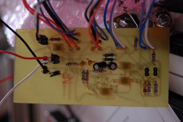
Here are the images of the green wired monstrosity
I didn't have double sided board at the time.
| Description: |
|
| Filesize: |
103.36 KB |
| Viewed: |
493 Time(s) |
| This image has been reduced to fit the page. Click on it to enlarge. |

|
| Description: |
|
| Filesize: |
110.43 KB |
| Viewed: |
481 Time(s) |
| This image has been reduced to fit the page. Click on it to enlarge. |
|
|
|
|
Back to top
|
|
|
dioioib
Joined: May 23, 2008
Posts: 56
Location: canada
|
Posted: Fri Jun 06, 2008 6:58 pm Post subject:
Ring Mod
Subject description: Latest development |
|
|
| Latest development, a few issues have been discovered. the input resistance for op-amp one and two are too high. I am bypassing these, which, gives a more usable sound after heavy amplification. I am currently working on a +/- 12v power supply. I figure the op-amps might need some more juice, however my power supply is outputting around +/- 8 or 9v. I am using a 115v to 12.6v transformer and 7912 and 7812 regulators. Any Ideas? |
|
|
Back to top
|
|
|
blue hell
Site Admin
Joined: Apr 03, 2004
Posts: 24423
Location: The Netherlands, Enschede
Audio files: 297
G2 patch files: 320
|
Posted: Sat Jun 07, 2008 6:01 am Post subject:
Re: Ring Mod
Subject description: Latest development |
|
|
| dioioib wrote: | | I am using a 115v to 12.6v transformer |
When it's a small transformer that you measured to give 12.6V when not connected to anything the transformer likely just is not up to the job, what voltage do you have after your rectifier / before the regulators / with the load present?
_________________
Jan
also .. could someone please turn down the thermostat a bit.
|
|
|
Back to top
|
|
|
dioioib
Joined: May 23, 2008
Posts: 56
Location: canada
|
| Posted: Sat Jun 07, 2008 4:00 pm Post subject:
Ring Modulator |
|
|
Well the voltage after regulation is about 8-9v
the voltage before the bridge rectifier (beads) is around 9v
Pre-transformer I am getting 112v AC should I try another fuse or just swap out the transformer for one with higher voltage? I have a 24v laying around somewhere. |
|
|
Back to top
|
|
|
blue hell
Site Admin
Joined: Apr 03, 2004
Posts: 24423
Location: The Netherlands, Enschede
Audio files: 297
G2 patch files: 320
|
| Posted: Sat Jun 07, 2008 4:51 pm Post subject:
|
|
|
Either a bigger one with 12 V or one with more voltage ... 24 * 1.4 = 33.6, + 20% = 37.3, - 1.4 = 35.9 ... 24 Volt is a bit much, you don't want to go over 35 V really worst case for regulator sanity ... 15 or 18 V would be Ok, or 12 V with plenty of transformer power.
What you have now before the regulators is too low, they need about 3V of over voltage to properly regulate.
_________________
Jan
also .. could someone please turn down the thermostat a bit.
|
|
|
Back to top
|
|
|
|

 Forum index » DIY Hardware and Software » Developers' Corner
