| Author |
Message |
KammutierSpule
Joined: Feb 07, 2008
Posts: 40
Location: Aveiro - Portugal
|
 Posted: Wed Nov 26, 2008 8:49 am Post subject:
Anyone PulseDensityModulation/DirectStreamDigital? Posted: Wed Nov 26, 2008 8:49 am Post subject:
Anyone PulseDensityModulation/DirectStreamDigital? |
  |
|
Any one have ever played with PDM?
I'm making some quick experiments, and I've sucesseful created a triangle wave .. I dont know how could I evaluate the quality of implementation... I can get pulse code in frekency about 300Khz (or less). still I think I get room from improvments...
how can I compare the "quality" of generated have? something like "bits per sample"? noise floor?
what should I measure with oscilloscope?
I ear some trys with PDM to make LFO oscilators.. but I think I can get some "pre configured simple waves(sin,tri,..)" for VCO use...
I'm right now with a 24F running at 14Mips.. using 8bits vars.. and can get only 300khz that its not much for a good quality.. I've read that sonny DSD runs 44100*64 = 2.8Mhz for each 1bit sample..
sugestions?
KS
Last edited by KammutierSpule on Thu Nov 27, 2008 5:57 am; edited 1 time in total |
|
|
Back to top
|
|
 |
JovianPyx

Joined: Nov 20, 2007
Posts: 1988
Location: West Red Spot, Jupiter
Audio files: 224
|
| Posted: Wed Nov 26, 2008 11:01 am Post subject:
|
|
|
Is there an advantage to pulse code modulation over a DAC?
What is a "24F" ?
You mention 8 bit - is that the word size for the data you use to do pulse code modulation? If so, isn't that a quality limitation? (or are you doing lo-fi intentionally?)
_________________
FPGA, dsPIC and Fatman Synth Stuff
Time flies like a banana.
Fruit flies when you're having fun.
BTW, Do these genes make my ass look fat?
corruptio optimi pessima
|
|
|
Back to top
|
|
|
KammutierSpule
Joined: Feb 07, 2008
Posts: 40
Location: Aveiro - Portugal
|
| Posted: Wed Nov 26, 2008 11:35 am Post subject:
|
|
|
| ScottG wrote: | Is there an advantage to pulse code modulation over a DAC?
What is a "24F" ?
You mention 8 bit - is that the word size for the data you use to do pulse code modulation? If so, isn't that a quality limitation? (or are you doing lo-fi intentionally?) |
Advantage you only need a microcontroller a resistor and a cap to get your analog output! ... no DAC.. it just use 1 pin of micro..
disavantage: lot of CPU power to stream bit output.. (but I think I can get better resultes with lower MIPS)
"24F" - PIC24F 16bits series...
8bits, yes and no  8bits are the size of vars.. (unsigned char) 8bits are the size of vars.. (unsigned char)
Btw.. I dont expect very hi fidelity.... and as far I can understand, there are no way to "converte quality from PCM to PDM" just using an equation..
maybe its measured by noise floor of the system.. and quality wave output...
... |
|
|
Back to top
|
|
|
cyberheater
Joined: Jun 03, 2008
Posts: 12
Location: Scotland
|
| Posted: Wed Nov 26, 2008 1:17 pm Post subject:
|
|
|
| Hi, I'm also interested in getting sound out of a pic. Could you post your code so I can have a look at it. Thanks. |
|
|
Back to top
|
|
|
urbanscallywag

Joined: Nov 30, 2007
Posts: 317
Location: sometimes
|
| Posted: Wed Nov 26, 2008 4:07 pm Post subject:
|
|
|
PCM and DSD are kind of opposites. DSD is sort of a fancy PWM, which your PIC has built into hardware. The problem is on a PIC the hardware PWM frequency doesn't really allow high quality audio. Using the PIC to do software PWM might get you closer (try something between 8 and 16 bit).
From my understanding, DSD has a word size equal to 1-bit, so if you're using 8-bit data you are more likely doing something closer to PWM than DSD. |
|
|
Back to top
|
|
|
KammutierSpule
Joined: Feb 07, 2008
Posts: 40
Location: Aveiro - Portugal
|
| Posted: Wed Nov 26, 2008 4:25 pm Post subject:
|
|
|
| cyberheater wrote: | | Hi, I'm also interested in getting sound out of a pic. Could you post your code so I can have a look at it. Thanks. |
There are not much info about PDM arround :\ I must check it better..
I found this example:
http://www.wiili.org/forums.html/GlovePIE:Pulsing_Algorithm
try understand it and how it makes the PDM..
the problem with PIC and PDM is that there is not enough power to get fo example "table sounds" with a hi frekency.. and good "precision?" ..
btw.. I think digital/analog music are very forgot... there a a hole between audophile pure analogs crcuits.. and CPU+good/hi-end DACs.. that I think isnt much covered...
I think uC could get out much components from analog circuits... and make a hybrid bridge between the analog and digital audio sound...
KS |
|
|
Back to top
|
|
|
picsynth
Joined: Oct 16, 2008
Posts: 27
Location: New Zealand
|
| Posted: Wed Nov 26, 2008 5:04 pm Post subject:
Sound out of a PIC |
|
|
The problem I think is that you need masses of speed for doing even simple wavforms anywhere nearing quality of what you can get out of an analog circuit.
Then once you are over the problem of producing a basic waveform you still need "room" ie bits of precision to alter the frequency, do things like frequency modulation etc...
In PICSynth I wanted to stick to low end (ie cheap) PICs : I basically decided to stick to square waves,
even then you need to run at 20 Mhz with 16 bit timers to be accurate enough.
The PICsynth waveshaper is pretty basic and changes the square wave to a staircase from which I derive a PW square and triangle.
I did have more steps in the staircase in early versions (ie like what a DAC would do) but found that actually a simple staircase had its own rather nice sound.
What would be perfect is some way to generate a real analog sawtooth, from which you could then get perfect triangles and pulse with a few op amps.
I have been studying the M110 chip used in JEN synths from the 70s - it generates a real analog sawtooth by outputing two things :
square wave + current proportional to frequency of the note. Using just 4 transistors results in a perfect (ie unlimited precision) sawtooth - very cool.
Kevin
PICSYNTH |
|
|
Back to top
|
|
|
KammutierSpule
Joined: Feb 07, 2008
Posts: 40
Location: Aveiro - Portugal
|
| Posted: Thu Nov 27, 2008 2:47 am Post subject:
Re: Sound out of a PIC |
|
|
| picsynth wrote: | The problem I think is that you need masses of speed for doing even simple wavforms anywhere nearing quality of what you can get out of an analog circuit.
Then once you are over the problem of producing a basic waveform you still need "room" ie bits of precision to alter the frequency, do things like frequency modulation etc... |
Yes, masses of horsepower ... or some good tricks too..
as I refer, i've got a ~CLK of 300Khz .. and generate a TRI shape of about 3.5Khz with about 64steeps I think its not muuch.. but still room from improvments...
and definitly, complex/hiFrequency wave forms can't be archived with a simple uC.. that mean, we can't do a very good "DAC" with PDM with this lowcost/speed/systems..
| picsynth wrote: |
In PICSynth I wanted to stick to low end (ie cheap) PICs : I basically decided to stick to square waves,
even then you need to run at 20 Mhz with 16 bit timers to be accurate enough. |
And that would be how much samplerate/bits per sample? or better.. if its a square wave, you got "infinity bits per sample" whats the sample rate? I think I made this calc before.. but you using PWM output? with PWM output I think you can get a good samplerate/precision
| picsynth wrote: |
The PICsynth waveshaper is pretty basic and changes the square wave to a staircase from which I derive a PW square and triangle.
I did have more steps in the staircase in early versions (ie like what a DAC would do) but found that actually a simple staircase had its own rather nice sound.
What would be perfect is some way to generate a real analog sawtooth, from which you could then get perfect triangles and pulse with a few op amps.
I have been studying the M110 chip used in JEN synths from the 70s - it generates a real analog sawtooth by outputing two things :
square wave + current proportional to frequency of the note. Using just 4 transistors results in a perfect (ie unlimited precision) sawtooth - very cool.
Kevin
PICSYNTH
|
I think "a few opamps" are still too much 4 transistors seams more OK.. maybe it still need some resistors..and Caps... but.. still too much components for me
I've found some where, a implementation of some kind of PDM with ADC feedback... it outputs the 1.bit data.. then measure it with ADC then feedback it... but I dont think it could get also good enough speed(frekency) and precision uhmm
uhmm what about some kind of hybrid "staircase" used in PDM? like.. insted of using 1 pin, use 2 or more pins with diferent resistors.. i.e: if the error delta is greater it loads with small resistor, if it a small error, it loads(or sink) is a small resistor..
that also need some more compute, but could give better aproximatino results with low "bit" frekency...
KS |
|
|
Back to top
|
|
|
KammutierSpule
Joined: Feb 07, 2008
Posts: 40
Location: Aveiro - Portugal
|
| Posted: Thu Nov 27, 2008 5:54 am Post subject:
|
|
|
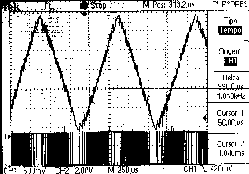
Where some pics from my currently (bad) implementation. :\
Bit rate: 250Khz -- 300Khz (using uC @ 14.7MIPS)
3.2V
RC circuit: R = 100K...200K? C = 0.2nF
CornerCutOff = 4Khz...8Khz
TriangleWaveFreq = 1Khz
| Description: |
|
| Filesize: |
6.76 KB |
| Viewed: |
17482 Time(s) |
|
| Description: |
|
| Filesize: |
10.41 KB |
| Viewed: |
17482 Time(s) |

|
| Description: |
|
| Filesize: |
6.04 KB |
| Viewed: |
17483 Time(s) |

|
|
|
|
Back to top
|
|
|
KammutierSpule
Joined: Feb 07, 2008
Posts: 40
Location: Aveiro - Portugal
|
| Posted: Thu Nov 27, 2008 6:00 am Post subject:
|
|
|
| Quote: | | Is there an advantage to pulse code modulation over a DAC? |
I'm so sorry,
my topic is wrong, I of course am talking about PDM and not PCM!  
| Quote: | | PCM and DSD are kind of opposites. DSD is sort of a fancy PWM, which your PIC has built into hardware. The problem is on a PIC the hardware PWM frequency doesn't really allow high quality audio. Using the PIC to do software PWM might get you closer (try something between 8 and 16 bit). |
Yes thats very true,
What I was suposed to mean is PDM =?= DSD!
I hope now we get clear 
KS |
|
|
Back to top
|
|
|
picsynth
Joined: Oct 16, 2008
Posts: 27
Location: New Zealand
|
| Posted: Thu Nov 27, 2008 5:35 pm Post subject:
|
|
|
So what I think you are attemping is Pulse Width Modulation (= pulse density modulation)
ie Average width of pulses is used to represent an analog value.
The wider the pulse the greater the analog value.
The resistor and cap are used to average the PWM signal/convert it to analog ?
In PICSynth I am not using PWM. Instead I am outputting 50/50 duty cycle square waves. I determine the length of period/2 using 16 bit timers - and toggle the outputs. |
|
|
Back to top
|
|
|
KammutierSpule
Joined: Feb 07, 2008
Posts: 40
Location: Aveiro - Portugal
|
| Posted: Thu Nov 27, 2008 6:41 pm Post subject:
|
|
|
| picsynth wrote: | | So what I think you are attemping is Pulse Width Modulation (= pulse density modulation) |
No, as far as I can understand is total diferent. PWM is diferent of PDM
PWM is as you describe:
| Quote: | ie Average width of pulses is used to represent an analog value.
The wider the pulse the greater the analog value.
The resistor and cap are used to average the PWM signal/convert it to analog ? |
Translated to "english" Pulse Width Modulation means, your are modulating the pulse width, making it wider or shorter, thats as you describe.
The PDM, also called? Digital Stream Modulation .. and I supose its also compared or called? Sigma-delta modulation.
Means Pulse Density Modulation, we module the pulse density, making it more often pulsed .. or less oftend pulsed.
| Quote: | | In PICSynth I am not using PWM. Instead I am outputting 50/50 duty cycle square waves. I determine the length of period/2 using 16 bit timers - and toggle the outputs. |
I think its PWM too.. with dutycycle 50%.. the diference is probably your are not using PWM module, but are using "software timmer/comparator" to make the pulse width/frekency.. You can do it too with PWM pic module.. you just need to reload timmer counters to setup desired frekncy, i supose.
One way to diferent the PWM and PDM is, in PWM the SUM(time on and time off) ==period and thats the time you have to setup a value (ie voltage)
and then, in next period time, you will vary the dutycycle to make a diferent value (voltage) and so on...
in PDM the current voltage(value) depends on last one (so its delta)
you sum a quanty of deltaV to last value and got the actual V..
lets compare,
PWM 50% value
|11110000|11110000|11110000|11110000|
PDM 50% value
.... |10101010|10101010|101010101|101010101|... and so on
and the best.. is that if the next value increase or decrease, it is delta/error adaptative.. correction are made bit a bit.... and not as PWM period .. a period..
I dont know much what frekency is need in a PWM approach to make it compare to a "PCM".. |
|
|
Back to top
|
|
|
picsynth
Joined: Oct 16, 2008
Posts: 27
Location: New Zealand
|
| Posted: Thu Nov 27, 2008 6:53 pm Post subject:
|
|
|
| Ah I see the difference now... so cursor 2 is showing the pulses, more pulses = higher analog value. |
|
|
Back to top
|
|
|
KammutierSpule
Joined: Feb 07, 2008
Posts: 40
Location: Aveiro - Portugal
|
| Posted: Thu Nov 27, 2008 8:03 pm Post subject:
|
|
|
| picsynth wrote: | | Ah I see the difference now... so cursor 2 is showing the pulses, more pulses = higher analog value. |
Well.. yes.. and no.. yes pulses.. or not.. I dont know what call it, but in this case pulses are "discret temporal stat of output beeing 1 ou 0 and time between a switch"
and if its 1, it charge the cap (at speed of RC) if its 0, it discharge the cap (at speed of RC)...
theorical, PDM output at a very high frequency, so it can easly be cutoff and get in the earing frekencys (<22K) ... but.. if you are draw a TRI shape, it wont probably be at 22K, (a think max in MIDI are 11Khz note).. so, differently from PCM, with PDM you get "smoth frekencys" at earing frekencus... |
|
|
Back to top
|
|
|
urbanscallywag
Joined: Nov 30, 2007
Posts: 317
Location: sometimes
|
| Posted: Thu Nov 27, 2008 8:12 pm Post subject:
|
|
|
OK so you are on the right track, DSD is a massively oversampled 1-bit ADC or DAC saying "higher" or "lower". I think almost every audio ADC/DAC uses one at the front end, but integrates the pulses using a multi-rate low pass filter to go from delta (error) to sigma delta (sum of error) and creates a PCM word based on the error sum.
I think you may have some better luck researching sigma delta DACs rather than pure DSD which works best if the source signal is a 1 bit stream (like SACD). |
|
|
Back to top
|
|
|
KammutierSpule
Joined: Feb 07, 2008
Posts: 40
Location: Aveiro - Portugal
|
| Posted: Sat Nov 29, 2008 5:49 am Post subject:
|
|
|
| urbanscallywag wrote: | | I think you may have some better luck researching sigma delta DACs rather than pure DSD which works best if the source signal is a 1 bit stream (like SACD). |
But.. I can have a DSD source signal too, instead having a wavetable with samples, have a waveBITtable, but that should be a huge amount of data :\
sigmaDeltaDACs, uhmm I fell much confused with that:
http://www.beis.de/Elektronik/DeltaSigma/DeltaSigma.html
seams Ill need more stuff, and that will be a "DIY DAC" uhm |
|
|
Back to top
|
|
|
urbanscallywag
Joined: Nov 30, 2007
Posts: 317
Location: sometimes
|
| Posted: Sat Nov 29, 2008 10:45 am Post subject:
|
|
|
Ah, you have a DSD input signal.
Let's see...
DSD bit rate = 44.1 ksamp/sec * 64 * 1 bit/samp = 2.8224 Mbit/sec
PCM (16-bit) rate = 44.1 ksamp/sec * 16 bit/sample = 705.6 kbit/sec
PCM (24-bit) rate = 44.1 ksamp/sec * 24 bit/sample = 1.0584 Mbit/sec
OK you're right that according to those over sample rates and bit depths DSD appears to use more memory than PCM. Can you do MATLAB/Octave simulations to see how low of an over sample rate you could get away with and still meet your specifications with DSD? |
|
|
Back to top
|
|
|
urbanscallywag
Joined: Nov 30, 2007
Posts: 317
Location: sometimes
|
| Posted: Sat Nov 29, 2008 10:47 am Post subject:
|
|
|
Nice plots by the way.  |
|
|
Back to top
|
|
|
KammutierSpule
Joined: Feb 07, 2008
Posts: 40
Location: Aveiro - Portugal
|
| Posted: Sat Nov 29, 2008 11:16 am Post subject:
|
|
|
| urbanscallywag wrote: | Ah, you have a DSD input signal.
Let's see...
DSD bit rate = 44.1 ksamp/sec * 64 * 1 bit/samp = 2.8224 Mbit/sec
PCM (16-bit) rate = 44.1 ksamp/sec * 16 bit/sample = 705.6 kbit/sec
PCM (24-bit) rate = 44.1 ksamp/sec * 24 bit/sample = 1.0584 Mbit/sec
OK you're right that according to those over sample rates and bit depths DSD appears to use more memory than PCM. Can you do MATLAB/Octave simulations to see how low of an over sample rate you could get away with and still meet your specifications with DSD? |
I've just sugested that I can have the DSD storage... right now what I do in this example , and what I have in mind is a tri wave, so, I'm calculating not only every bit sample, and also a "line equation" with x and y steps and delta errors.. so.. its real synthetized |
|
|
Back to top
|
|
|
urbanscallywag
Joined: Nov 30, 2007
Posts: 317
Location: sometimes
|
| Posted: Sat Nov 29, 2008 11:28 am Post subject:
|
|
|
Oh I see.
Well either way I would try and do some simulations to verify that you've hit the limit of what the PIC is capable or if there's more performance to squeeze out.
Or else look into sigma-delta like most every other system uses (though I do find what you're doing interesting). |
|
|
Back to top
|
|
|
|

 Forum index » DIY Hardware and Software » Microcontrollers and Programmable Logic
