| Author |
Message |
synaesthesia

Joined: May 27, 2014
Posts: 291
Location: Germany
Audio files: 85
|
 Posted: Sun Jan 25, 2015 8:43 am Post subject:
Harmonic Divider Posted: Sun Jan 25, 2015 8:43 am Post subject:
Harmonic Divider
Subject description: multiple simulataneous output frequencies from a single input frequency |
  |
|
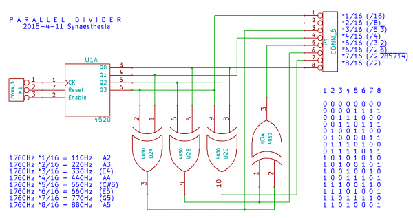
One thing I wanted to build for quite a while is a divider that creates multiple divisions of a single input frequency that can be used at the same time. The famous melody generator generates divisions, but only one division is available at one time. I wanted multiple division simultaneously, like from an octave generator. (Has anybody built something similar already that uses a simple circuit?)
My first idea was to use a 4022 and a diode-OR gates to combine the outputs to regular square wave patterns, but that didn't sound too nice. So I settled for a simpler goal first: a divider that creates two output frequencies from one input frequency. Dividers are easy to build using a shift register that is wired as a Johnson-Counter. With half of a 4015 and one NAND gate you can create all divisions from 2 to 8, plus a division by 2.5.
| Code: |
NAND Q0+Q0 divide by 2 NAND Q1+Q0 divide by 3 NAND Q2+Q0 divide by 2 NAND Q3+Q0 divide by 2.5
NAND Q0+Q1 divide by 3 NAND Q1+Q1 divide by 4 NAND Q2+Q1 divide by 5 NAND Q3+Q1 divide by 6
NAND Q0+Q2 divide by 2 NAND Q1+Q2 divide by 5 NAND Q2+Q2 divide by 6 NAND Q3+Q2 divide by 7
NAND Q0+Q3 divide by 2.5 NAND Q1+Q3 divide by 6 NAND Q2+Q3 divide by 7 NAND Q3+Q3 divide by 8
|
The idea then was to use two 4015 shift registers and create two dividers from it. Now, which two ratios to choose for each of the four combinations? I settled for combinations that are harmonic. The dividers used here are either 6&5, 5&4, 4&3, or 3&2. The latter is actually implemented as 6&4. Of course you immediately recognize those ratios. They are for a minor third, a major third, a perfect fourth and a perfect fifth. A 4052 analog switch is then used to select the two divisions for the input frequency. You find this harmonic divider building block in the blue box in the schematic.
As the divider alone would not sound too interesting, I put a bit of additional circuitry around it. Originally, I only wanted to enumerate the output frequencies using a 4040 counter. Then I thought about how a mix of the two output frequencies would sound and tried a NAND and XOR gate. That was nice. Then I used a RS-Flipflop built from the two remaining NAND gates of the 4093 and was surprised. The mixed frequency sometimes changes. I believe this is because of the relative phase the two input square waves can have. Need to look a bit deeper into this. For now I am happy about the effect.
The recording was made with a constant pitch and tempo. You recognize the basic pattern of the four ratios. With the wiring used in the schematic there are sixteen tones played for each selected ratio. The tones alternate between the two output frequencies and the mix of both using a 4053 analog switch. You can change the tap points from the 4040 counter to get different sequence lengths and pattern orders. The result is a pretty addictive beat that goes on and on, and sometimes surprises you with a variation.
| Description: |
|
| Filesize: |
41.43 KB |
| Viewed: |
957 Time(s) |
| This image has been reduced to fit the page. Click on it to enlarge. |

|
| Description: |
|

Download (listen) |
| Filename: |
HarmonicDivider.mp3 |
| Filesize: |
1.9 MB |
| Downloaded: |
1196 Time(s) |
|
|
|
Back to top
|
|
 |
revtor

Joined: Oct 05, 2005
Posts: 79
Location: NewJersey, USA
|
| Posted: Mon Jan 26, 2015 1:04 pm Post subject:
|
|
|
Nice! yes that melody is quite a hook!
~Steve
_________________
beep blurp flurrrp fiszzzzp pow bakka wakka wakka -A synth freaks mental notes. |
|
|
Back to top
|
|
|
synaesthesia
Joined: May 27, 2014
Posts: 291
Location: Germany
Audio files: 85
|
| Posted: Thu Jan 29, 2015 1:55 pm Post subject:
|
|
|
Update regarding the variations: it's not the RS-FlipFlop. It happens with an XOR as well. It is indeed the phase shift between f1 and f2. Each time the divider ratio is changed the shift registers start with different initial (current) values. That produces phase shifted outputs that stay in sync until the dividers change again.
Using the combination of divide by 4 and 6 as an example, there are indeed two possible phase shifts that would generate two different outputs through an XOR or NAND.
| Code: | 110011001100110011001100 /4
111100111100111100111100 /6
001111110000001111110000 XOR
001111110011001111110011 NAND
110011001100110011001100 /4
111001111001111001111001 /6
001010110101001010110101 XOR
001110110111001110110111 NAND |
This also explains why not all combinations produce variations. For example, I could not find a phase shift between a signal that was divided by 4 and 5 where this happens. |
|
|
Back to top
|
|
|
synaesthesia
Joined: May 27, 2014
Posts: 291
Location: Germany
Audio files: 85
|
|
|
Back to top
|
|
|
|

 Forum index » DIY Hardware and Software » Lunettas - circuits inspired by Stanley Lunetta