| Author |
Message |
Dr. K
Joined: Jan 15, 2020
Posts: 52
Location: wisconsin
|
 Posted: Fri Jan 03, 2025 4:54 pm Post subject:
Question about diode vs. resistive mixing Posted: Fri Jan 03, 2025 4:54 pm Post subject:
Question about diode vs. resistive mixing |
  |
|
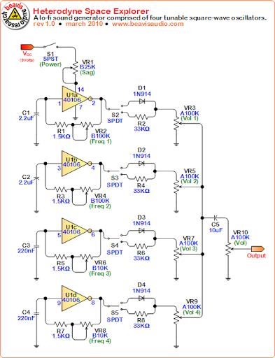
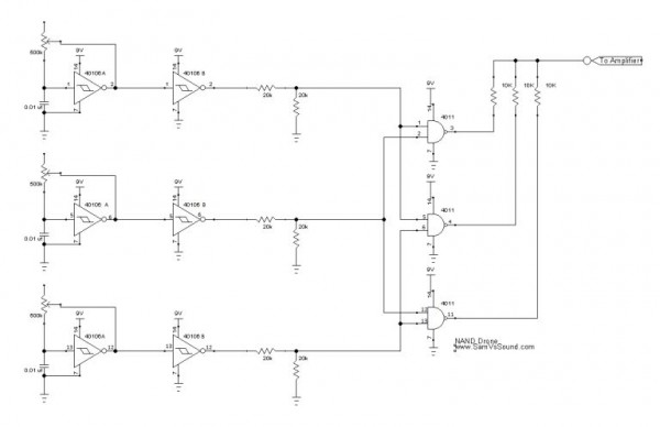
I built a device very similar to the one in the attachment. I used 555 oscillators (left hand side) because they are easy to run with voltage control. But the NAND stage is the same.
Honestly, the results were rather boring. The device works, but nothing very interesting.
So I tried replacing the mixer resistors with small signal diodes, thinking it should accentuate the sum and difference frequencies, and produce a more "electronic" sound. Unfortunately, with diode mixing, the sound to my ears is virtually identical.
I dug around, and in Nic Collins book, on the section regarding diode and resistor mixing, he says that if the diode mixing "does not work with your amplifier", that you can try tying the outputs of the diodes to ground via a 10k resistor. I have no idea what "does not work with your amplifier" means. As I mentioned, I am getting a healthy signal out of my amp. The tone control pots work. The input oscillators all work when you connect them before the NAND stage. As far as I can tell, everything is working. I'm just curious why the diode coupled output doesn't sound different than the resistor network.
I wanted to make the outputs of the NAND stage switchable (similar to the "heterodyne space explorer") but if it's going to sound identical, there would be little point.
Any advice on the matter.
| Description: |
|
| Filesize: |
79.07 KB |
| Viewed: |
6547 Time(s) |
|
| Description: |
|
| Filesize: |
25.3 KB |
| Viewed: |
90 Time(s) |
| This image has been reduced to fit the page. Click on it to enlarge. |
|
|
|
|
Back to top
|
|
 |
blue hell
Site Admin

Joined: Apr 03, 2004
Posts: 24496
Location: The Netherlands, Enschede
Audio files: 298
G2 patch files: 320
|
| Posted: Fri Jan 03, 2025 8:03 pm Post subject:
|
|
|
Ok .. some quick (and possibly arrogant and nitwit -as i-ve never built such a thing) thoughts .. after a quick look 
You mix with diodes, but you feed them with unipolar signals (positive only) and those signals have a fixed amplitude (as they are square like signals).
Although diodes are not linear and might behave differently to resistors when the current trough them varies, in the sketched mixer setups it is all fixed - this means that the diodes will just behave as resistors.
And probably they will be like relatively small valued resistors, and then the actual summing takes place into a resistor- in the top one schematic this is clearer to see with the pots and all, but on the bottom one there will be (an undrawn) resistance on the output too (belonging to a follwing amplifier - this may explain the 'if your amplifer' remark, but more details would be needed).
So basically this will mean that in these two cases diodes behave not really different from resistors - it maybe a tad louder - it may give a bit of distortion (when the signals are not perfect squares), but I would expect it to be marginal.
I've seen it here before - without any thought from my side at all really - and now wonder where this idea of diode mixing comes from - it is being using in high frequency stuff but with a different purpuse (to get an LF signal modulated onto a HF one - or reverse), but that can not be --it-- and from a quick theoretic view see not much happening in the two examples given here.
Anyway, my cents - I'm not sure how many - soo shoot me please 
_________________
Jan
also .. could someone please turn down the thermostat a bit.
 |
|
|
Back to top
|
|
|
Dr. K
Joined: Jan 15, 2020
Posts: 52
Location: wisconsin
|
| Posted: Sat Jan 04, 2025 5:31 am Post subject:
|
|
|
Thanks for the info. I was doing some reading on diodes as resistors.
I'm trying to explore this further as Nic Collins in his book, and the schematic from Beavis Audio both mentioned diodes as half wave rectifiers, that should (when being used as a mixer) accentuate sum and difference frequencies.
I'm not sure how that should sound--but I was surprised in my test that it sounded identical to resistor mixing.
I'll have to mess with it some more |
|
|
Back to top
|
|
|
blue hell
Site Admin
Joined: Apr 03, 2004
Posts: 24496
Location: The Netherlands, Enschede
Audio files: 298
G2 patch files: 320
|
| Posted: Sat Jan 04, 2025 6:27 am Post subject:
|
|
|
My reasoning was not that diode mixing would not work at all - thre are reasons it does not much here :
- Yes they are half wave rectifiers, but when fed a positive only voltage there will be no negative signal half to cut cut off - there is nothing to rectify.
- Also when the signal is block shaped the non-linearity of the diode has no way to color the signal (alter it's shape). As there either is some voltage or none the non linearity of the diode does something static - it behaves like a small resistor.
Diodes would make a difference for non square bipolar signals.
_________________
Jan
also .. could someone please turn down the thermostat a bit.
|
|
|
Back to top
|
|
|
Dr. K
Joined: Jan 15, 2020
Posts: 52
Location: wisconsin
|
| Posted: Sat Jan 04, 2025 3:28 pm Post subject:
|
|
|
Ah, that makes sense-if ths diode is oriented and you only have positive current, theirs nothing to block.
I'm curious then, why do circuits (like the beavis audio circuit) utilize resistor/diode switching? Are they in some way floating the signal, so it can swing above and below 0?
Thanks for the straight forward explanation. My background is chemistry. I'm a newbie/hack/old time ham radio nerd. Trying to learn, but the learning curve is a bit of a bugger |
|
|
Back to top
|
|
|
trackhed
Joined: Sep 16, 2015
Posts: 9
Location: California
|
Posted: Sat Mar 15, 2025 6:54 am Post subject:
Some more non cents
Subject description: Maybe just one |
|
|
| Could this somehow be related to virtual grounding? Maybe using diodes somehow is more(or less) stable than resistors in confusing bipolar circuits. |
|
|
Back to top
|
|
|
PHOBoS

Joined: Jan 14, 2010
Posts: 5881
Location: Moon Base
Audio files: 709
|
| Posted: Sat Mar 15, 2025 12:24 pm Post subject:
|
|
|
consider the following:
The NAND drone circuit has 3 signals coming out of the NAND gates that are mixed together.
If you use diodes for this you are creating a logic OR gate* and if at least one of the signals is high the output will be high. Having more than one output being high
won't make any change to the output voltage and only when all the signals are low the output will be low. ie the output is a digital signal.
*there should be a resistor to GND to function properly, as Jan mentioned that could be your amp.
If you use resistors it's a different story as you are now creating a voltage divider which can create multiple voltages.
- when all the signals are low the result is 0V/low
- when one of the signals is high the result is 1/3 of the signal voltage
- when two of the signals are high the result is 2/3 of the signal voltage
- when all 3 of the signals are high the result is the same as the signal voltage/high
this is assuming all the resistors that are used to mix the signals together have the same value, if you use different values you can get more variation in the output voltage.
Either way the result is a stepped output voltage. You can go a step further and use an R2R network to mix the signals together.
If you don't hear much of a difference this could be because the value of the mix resistors is too high compared to the input impedance of the amp you connect it to.
Ideally you'd buffer the signal before going into the amp. if you have an oscilloscope you could have a look at the signal to see what the difference is.
sidenote: in the NAND drone schematic the use of the 20K resistors between the inverters and the NAND gates is pretty much the opposite
of what you'd want for a digital circuit. There are no resistors needed when connecting a single output to one or more inputs unless
you need a level shift because you are working with different supply voltages and/or use a a device with a tri-state output.
In the case of the NAND drone it creates a signal at 1/2 the supply voltage which is not a clear high or low level.
sidesidenote: I used a variation of this in the XOA mixer, which uses a mux instead of diodes for digital mixing and resistors for analog mixing.
_________________
"My perf, it's full of holes!"
http://phobos.000space.com/
SoundCloud BandCamp MixCloud Stickney Synthyards Captain Collider Twitch YouTube |
|
|
Back to top
|
|
|
|

 Forum index » DIY Hardware and Software » Lunettas - circuits inspired by Stanley Lunetta
