| Author |
Message |
Dr. K
Joined: Jan 15, 2020
Posts: 52
Location: wisconsin
|
 Posted: Mon Apr 14, 2025 12:44 pm Post subject:
Op Amp to split sequencer voltage? Posted: Mon Apr 14, 2025 12:44 pm Post subject:
Op Amp to split sequencer voltage? |
  |
|
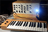
I've spent the past weeks building a kind of drone-synth. It has 3 555 based and 3 4046 based VCOs. The device is set up with the VCOs switchabe, so that 3 of them feed 3 NAND gates. The individual oscillators all work, and the wiring so far seems good (ie, selector switches for 555/4046).
I'm trying to figure out a way to take my sequencer output and use it to drive all 3 VCO inputs. While I was digging around for answers, I stumbled upon a schematic for a Synthrotek Sequence 8. It boasts 3 CV outputs, each with limiter pots, so each CV can be different. They used a TLV274, but it was configured like my crude drawing here.
I was wondering if I could use the same trick, but with an LM324 quad op amp. Use 1 non-inverting input to drive 3 non-inverting inputs (all set up as unity gain)? It seems to me it should work alright.
The Synthrotek schematic had the limiter pots in front of the op amp stages (as in my drawing), but I was curious why they are in front of, and not after, the op-amp stages.
Thanks again for all the wisdom.
John
| Description: |
|
| Filesize: |
1.26 MB |
| Viewed: |
65 Time(s) |
| This image has been reduced to fit the page. Click on it to enlarge. |

|
|
|
|
Back to top
|
|
 |
PHOBoS

Joined: Jan 14, 2010
Posts: 5862
Location: Moon Base
Audio files: 709
|
|
|
Back to top
|
|
|
Dr. K
Joined: Jan 15, 2020
Posts: 52
Location: wisconsin
|
| Posted: Mon Apr 14, 2025 1:15 pm Post subject:
|
|
|
I'll breadboard it up before I commit to anything.
I just broke down and ordered an import o-scope. Trying to build oscillator circuits without that has been driving me nuts! My only diagnostic is a Fluke multi-meter. Don't get me wrong--I use that thing constantly while building. Trying to catch errors as they arise and avoid trouble shooting at the end.
Any thoughts as to why the limiter pots are placed before the op-amps rather than after? (this drawing was largely inspired by the Synthrotek schematic, and they put the pots as shown).
Anyway, should be a cool device when it's up and running. With adjustable CV inputs, resistor/diode coupling of the nand-outputs, and base frequency pots, their would be a ton of sonic possibilities.
The original nand-drone I built used 3 555 oscillators. You could get cool sounds by carefully adjusting the frequency pots. But that got boring in a hurry. Having it under CV control would open up a lot of fun opportunities. |
|
|
Back to top
|
|
|
Cynosure
Site Admin

Joined: Dec 11, 2010
Posts: 1007
Location: Toronto, Ontario - Canada
Audio files: 82
|
| Posted: Mon Apr 14, 2025 1:49 pm Post subject:
|
|
|
| Dr. K wrote: | | Any thoughts as to why the limiter pots are placed before the op-amps rather than after? |
I think that it is so that those pots don't interfere with whatever they are connected to. The opamps are acting as a buffer to isolate that part of the circuit from the next part.
_________________
JacobWatters.com |
|
|
Back to top
|
|
|
Dr. K
Joined: Jan 15, 2020
Posts: 52
Location: wisconsin
|
| Posted: Mon Apr 14, 2025 1:54 pm Post subject:
|
|
|
Ah, I see. the first op-amp stage isolates the sequencer from the everything down stream. Then the voltage modifications are made with the pots, and the next op amp stage isolates all down stream oscillators.
I'm looking forward to my o-scope coming in. I'm trying to teach myself theory. It goes ok, but being able to visualize what I'm doing and make actual measurements would demystify a lot of it. |
|
|
Back to top
|
|
|
Cynosure
Site Admin
Joined: Dec 11, 2010
Posts: 1007
Location: Toronto, Ontario - Canada
Audio files: 82
|
| Posted: Mon Apr 14, 2025 8:11 pm Post subject:
|
|
|
Yes - that is exactly what is happening in that schematic.
I actually went a long time without an oscilloscope. For several years, I just used an oscilloscope app on my computer, and an audio interface.
It did well for audio, but it didn't help for envelope generators and LFOs.
It's nice to have the proper tools for the job.
_________________
JacobWatters.com |
|
|
Back to top
|
|
|
Grumble
Joined: Nov 23, 2015
Posts: 1318
Location: Netherlands
Audio files: 30
|
|
|
Back to top
|
|
|
Dr. K
Joined: Jan 15, 2020
Posts: 52
Location: wisconsin
|
| Posted: Sun Apr 20, 2025 5:08 am Post subject:
|
|
|
Thank you for the schematic. I'm trying to study up and learn op-amp circuits. Can you tell me what the benefit of using the inverting input would be?
It also brings up another question. I've seen op-amp circuits set up for unity gain that didn't use resistors in the input or feedback (ie, wired with R~0), or also with resistors of the same value. Why are they sometimes used and sometimes not?
thanks again for the idea. |
|
|
Back to top
|
|
|
Grumble
Joined: Nov 23, 2015
Posts: 1318
Location: Netherlands
Audio files: 30
|
| Posted: Sun Apr 20, 2025 11:55 am Post subject:
|
|
|
If you go here:
https://www.falstad.com/circuit/circuitjs.html
You can build circuits and test them out, so you can play with resistor values etc.
That said: The attennuverter is a very smart circuit, with the potmeter you can change the gain from -1x to 1x using this circuit:
https://tinyurl.com/22gn53yd
Why do some unity gain circuits use resistors and others not:
If you have a circuit where the source is connected to the + input and the -input is connected to the output, then the load as seen from the source is very high impedance, as high as the datasheet says (not seldom >100Megohm) but not all opamps are good in unity gain connected this way...
Check this out:
http://sim.okawa-denshi.jp/en/opampkeisan.htm
But you are low in component count, thus cheaper.
So if they use a circuit where from the -input of the opamp there are two resistors with the same value connected to the output and the other to gnd, there the source is connected to the +input of the opamp and also the input impedance seen from the source is very high.
Sometimes there is also a resistor connected between the source and the +input to compensate for temperature variations and keep the common mode rejection ratio (CMRR) high.
Another benefit connecting the opamp in unity gain this way is that you can place a capacitor in parallel with the resistor going from -input to output thus creating a filter (high cut-off).
And.... the gain is 2x
If you change position of the gnd and source, you have unity gain, but the signal is inverted... I wonder... is this still unity gain??
_________________
my synth |
|
|
Back to top
|
|
|
|

 Forum index » DIY Hardware and Software » Lunettas - circuits inspired by Stanley Lunetta


