| Author |
Message |
cslammy
Joined: Apr 27, 2018
Posts: 206
Location: USA
Audio files: 1
|
 Posted: Fri Dec 14, 2018 8:15 am Post subject:
Need CMOS patcher with a lot of I/O. Ideas? Posted: Fri Dec 14, 2018 8:15 am Post subject:
Need CMOS patcher with a lot of I/O. Ideas? |
  |
|
I need to create a CMOS patch bay for a Lunetta noise project.
There are 12 sources and 2x 5 input bays that need to be patched.
I was going to use 4051B's controlled by Arduino NANO but even at that (8 to 1) it'd be a lot of chips, at least 10 + nano + mux + buffers + power which means a fair amount of PCB space.
Is there another way to do this with lower parts count? So, Some sort of super 4051?
_________________
Visit my AUDIODIWHY blog and website |
|
|
Back to top
|
|
 |
JovianPyx

Joined: Nov 20, 2007
Posts: 1988
Location: West Red Spot, Jupiter
Audio files: 224
|
| Posted: Fri Dec 14, 2018 8:50 am Post subject:
|
|
|
There is CD74HC4067 which is a 16 channel analog mux. It works with a supply voltage from 2 to 6 volts and it is surface mount. That really only combines 2 eight channel analog muxes (plus a 2 channel analog mux) into one chip. You didn't post a schematic of your design so I can't see it to comment on possible simplifications.
http://www.ti.com/lit/ds/symlink/cd74hc4067.pdf <-- datasheet.
Even at that, it will likely be "too many parts". You can either use "too many parts" or reduce your design.
Maybe others have a more clever design.
_________________
FPGA, dsPIC and Fatman Synth Stuff
Time flies like a banana.
Fruit flies when you're having fun.
BTW, Do these genes make my ass look fat?
corruptio optimi pessima
|
|
|
Back to top
|
|
|
PHOBoS

Joined: Jan 14, 2010
Posts: 5947
Location: Moon Base
Audio files: 709
|
|
|
Back to top
|
|
|
cslammy
Joined: Apr 27, 2018
Posts: 206
Location: USA
Audio files: 1
|
| Posted: Fri Dec 14, 2018 9:39 am Post subject:
|
|
|
| PHOBoS wrote: | | I'd need a bit more info on what exaclty you like to achieve. Also, are the signals digital ? |
yes it'd help for the group to know what I'm trying to do

Sorry schem is here:
Reverselandfill NOISE!
http://www.reverselandfill.org/wp-content/uploads/2017/03/noise5gschem.zip
I did a board swap with martijn and promised to mod his board. 
Trying to use a switcher instead patch bay, so, what is there now (solder wires to form patching w something controllable from an MCU.
_________________
Visit my AUDIODIWHY blog and website |
|
|
Back to top
|
|
|
PHOBoS
Joined: Jan 14, 2010
Posts: 5947
Location: Moon Base
Audio files: 709
|
| Posted: Wed Dec 19, 2018 4:13 pm Post subject:
|
|
|
ok, I understand what you want to do now.
Since all the signals are digital you could route (and even process) them through the arduino itself. For this you can use shiftregisters for the inputs
(74HCT165) and outputs (74HCT595) or wire some directly to the arduino depending on how many pins you have available. Of course the supply voltage
of the whole circuit has to be 5V if you do that. Actually, you could just use level shifters between the in and outputs and power the rest of the circuit of a
different voltage.
Using muxes is an easier solution coding wise and you don't have the risk of the arduino doing anything to the sound. However, you'd need a LOT of chips
if you want every possibility. Actually some kind of matrix would be preferred but that still leaves 120 nodes which is an awful lot to control. So yeah, I think
routing signals through the arduino might be the best solution.
_________________
"My perf, it's full of holes!"
http://phobos.000space.com/
SoundCloud BandCamp MixCloud Stickney Synthyards Captain Collider Twitch YouTube |
|
|
Back to top
|
|
|
cslammy
Joined: Apr 27, 2018
Posts: 206
Location: USA
Audio files: 1
|
| Posted: Wed Dec 19, 2018 4:40 pm Post subject:
|
|
|
| PHOBoS wrote: | ok, I understand what you want to do now.
I think
routing signals through the arduino might be the best solution. |
Thanks Phobos
I'm considering trying to fab a VCS3 like pegboard for this project, Mostly to see if I can figure out how to do it from surplus parts.
Failing that, I will use I/O directly on the MCU, yes, too many chips needed otherwise.
_________________
Visit my AUDIODIWHY blog and website |
|
|
Back to top
|
|
|
PHOBoS
Joined: Jan 14, 2010
Posts: 5947
Location: Moon Base
Audio files: 709
|
| Posted: Wed Dec 19, 2018 5:39 pm Post subject:
|
|
|
good luck with that (I mean that in the most positive way)
You could of course also use a matrix of switches. Latching pushbuttons (with an LED or mechanical indicator) would be nice for this.
Hmm those old style radio buttons would actually be ideal (like this but with 12 switches), so it mechanically limits it to one output
per input. Adding multiple signals is probably extra fun though (don't forget to add diodes).
_________________
"My perf, it's full of holes!"
http://phobos.000space.com/
SoundCloud BandCamp MixCloud Stickney Synthyards Captain Collider Twitch YouTube |
|
|
Back to top
|
|
|
cslammy
Joined: Apr 27, 2018
Posts: 206
Location: USA
Audio files: 1
|
| Posted: Wed Dec 19, 2018 6:01 pm Post subject:
|
|
|
| PHOBoS wrote: | good luck with that (I mean that in the most positive way)
You could of course also use a matrix of switches. Latching pushbuttons (with an LED or mechanical indicator) would be nice for this.
Hmm those old style radio buttons would actually be ideal (like this but with 12 switches), so it mechanically limits it to one output
per input. Adding multiple signals is probably extra fun though (don't forget to add diodes). |
I'm talking about trying to come up with something like what's on the Putney/VCS3. I understand buying those, if they can even be found, is really expensive so I may try to DIY it with test probes and PCB's.
I like the radio car button idea as well; Lots of ways to go here...since the CMOS noise is kinda "new" I want to interface to be kinda "old". Ill blog what I come up with. Thanks.
_________________
Visit my AUDIODIWHY blog and website |
|
|
Back to top
|
|
|
gabbagabi

Joined: Nov 29, 2008
Posts: 652
Location: Berlin by n8
Audio files: 23
|
| Posted: Thu Dec 20, 2018 3:26 am Post subject:
|
|
|
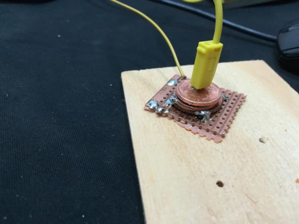
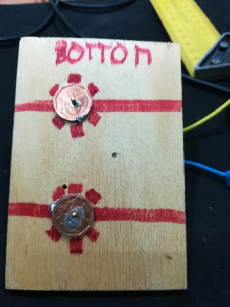
/* two cents start */
the basic idea was to solder some coins on top of each other to get a socket (pic1)
for the matrix you now could imagine a two-sided PCB where you have solderpoints for the coins on each side, one side vertical, other side horizontal connected
if you then plug a banana plug, you have a connection, right?
i would expect that some offset disances here and there are needed
maybe the use of two PCB on top of each other to give it more strength?
/* two cents end*/
| Description: |
|
| Filesize: |
53.43 KB |
| Viewed: |
537 Time(s) |
| This image has been reduced to fit the page. Click on it to enlarge. |
|
| Description: |
|
| Filesize: |
59.91 KB |
| Viewed: |
542 Time(s) |
| This image has been reduced to fit the page. Click on it to enlarge. |

|
| Description: |
|
| Filesize: |
53.29 KB |
| Viewed: |
541 Time(s) |
| This image has been reduced to fit the page. Click on it to enlarge. |
|
|
|
|
Back to top
|
|
|
cslammy
Joined: Apr 27, 2018
Posts: 206
Location: USA
Audio files: 1
|
| Posted: Thu Dec 20, 2018 9:56 am Post subject:
|
|
|
Interesting g.gabba as always. Coins eh? You always have good ideas!
I am going to mess with this in different ways. I understand that the Ghielmetti matrix costs a fortune (hundreds of dollars?) if you can find it at all....which I can't. So I'll see if I can some up w/ something DIY. If I come up with anything that sorta works I will write it up on the blog.
_________________
Visit my AUDIODIWHY blog and website |
|
|
Back to top
|
|
|
cslammy
Joined: Apr 27, 2018
Posts: 206
Location: USA
Audio files: 1
|
| Posted: Thu Dec 20, 2018 5:51 pm Post subject:
|
|
|
OK I am starting to mess with Cmos 4051s mux, maybe for this.
This question arises from trying to build a real world module out of the Simulation at the bottom of this post:
http://audiodiwhy.blogspot.com/2018/12/virtual-bread-board-simulate-your-trip.html
Question:
if you guys were designing a circuit for a modular synth using a 4051 to switch between CV's would you buffer:
--The signals coming into the 4051 (not logic--I mean the CV's I am selecting with the 4051)
--The signal coming out of the 4051
--Or both?
I figure I need to buffer the output? So one TL071?
My reasoning, and yes, I may not know what I am talking about 
The inputs of the 4051 are FETs and so are the TL071's inverting and non inverting inputs. But I'd use as a want to make sure nothing downstream from the 4051 sucks too current out of the switch, due to a ground fault or other issue with another module fed by the 4051 switch.
hence the buffer, single TL071 let's say.
What do you think?
_________________
Visit my AUDIODIWHY blog and website |
|
|
Back to top
|
|
|
Steveg

Joined: Apr 23, 2015
Posts: 184
Location: Perth, Australia
|
| Posted: Fri Dec 21, 2018 3:52 am Post subject:
|
|
|
Hi cslammy, For CMOS switches and muxes like the 4051 you don't need any buffering as long as the chips fanout limitations are respected. If you want it for isolation you could use a 4050 for digital signals or a single transistor wired as an emitter follower for analog signals.
If you don't need full any-to-any matrix switching you might consider having a number of busses. A pair of 4051s connected pin 3 to pin 3 gives you a single bus with 8 inputs and 8 outputs. If you put a transistor between the two 4051s you also have isolation. You can connect a single source or sink to several busses and add more as needed. |
|
|
Back to top
|
|
|
CHRISKELLY
Joined: Apr 08, 2018
Posts: 103
Location: England
Audio files: 3
|
| Posted: Fri Dec 21, 2018 4:23 am Post subject:
|
|
|
| Some great advice there Steve |
|
|
Back to top
|
|
|
blue hell
Site Admin

Joined: Apr 03, 2004
Posts: 24652
Location: The Netherlands, Enschede
Audio files: 326
G2 patch files: 320
|
| Posted: Fri Dec 21, 2018 6:34 am Post subject:
|
|
|
Also .. when doing matrix stuff .. I've no idea if you can actually buy such chips .. but there used to be CMOS matrix switches / cross point switches (used for telephony) ... ah AD has something they still make : https://www.analog.com/en/products/ad75019.html - 16 x 16, not like really cheap tho. And my CMOS book suggests CD22100 for a 4 x 4 switch or CD22101/CD22102 for a dual 4x4 (for use with balanced signals).
_________________
Jan
also .. could someone please turn down the thermostat a bit.
 |
|
|
Back to top
|
|
|
piedwagtail

Joined: Apr 15, 2006
Posts: 297
Location: shoreditch
Audio files: 3
|
| Posted: Fri Dec 21, 2018 1:26 pm Post subject:
|
|
|
Could be done with a cheap chinese CPLD development board; my adaption of Richarius's 4015 matrix used as such.
http://electro-music.com/forum/topic-69221
the last post is the actual programming file. Muxs are available as schematic symbols.
VHDL or Verilog is the proper method but Lunettas are simple enough to string together in the schematic programmer.
R |
|
|
Back to top
|
|
|
ixtern
Joined: Jun 25, 2018
Posts: 145
Location: Poland
|
| Posted: Fri Dec 21, 2018 2:52 pm Post subject:
|
|
|
| Blue Hell wrote: | | Also .. when doing matrix stuff .. I've no idea if you can actually buy such chips .. but there used to be CMOS matrix switches / cross point switches (used for telephony) ... ah AD has something they still make : https://www.analog.com/en/products/ad75019.html - 16 x 16, not like really cheap tho. And my CMOS book suggests CD22100 for a 4 x 4 switch or CD22101/CD22102 for a dual 4x4 (for use with balanced signals). |
I've bought less than year ago MM22100 (CD22100) locally so they are still somewhere available. Done nothing with them yet but I am still thinking... |
|
|
Back to top
|
|
|
synaesthesia

Joined: May 27, 2014
Posts: 291
Location: Germany
Audio files: 85
|
| Posted: Sat Dec 22, 2018 2:38 am Post subject:
|
|
|
You still want to patch the connections manually, but get rid of long cables, right? How about using one double male pin header per input (length is given by the number of possible inputs) and make the connection with a small jumper pin. Connect all inputs to the pins on one side of the header. The pins on the other side are connected together as output. Just take care that you only use one jumper pin per row.
BTW, the schematic you have has a short between Q1 and Q3 of the 4040 IC. That doesn't seem right. |
|
|
Back to top
|
|
|
fetideye

Joined: Jun 22, 2015
Posts: 27
Location: Netherlands
|
| Posted: Tue Dec 25, 2018 8:42 am Post subject:
|
|
|
it is not the most usual practice, I know. but it is intentional.
by patching the 4040 outputs together there are cool interactions in the sound.
one day I'll try to achieve this in a more sophisticated way, for example by automated mixing / switching (4060) or maybe buffered by diodes / transistors. |
|
|
Back to top
|
|
|
Grumble
Joined: Nov 23, 2015
Posts: 1320
Location: Netherlands
Audio files: 30
|
|
|
Back to top
|
|
|
piedwagtail
Joined: Apr 15, 2006
Posts: 297
Location: shoreditch
Audio files: 3
|
|
|
Back to top
|
|
|
Grumble
Joined: Nov 23, 2015
Posts: 1320
Location: Netherlands
Audio files: 30
|
| Posted: Wed Dec 26, 2018 11:17 am Post subject:
|
|
|
I didn’t made it, just provided the link 
_________________
my synth |
|
|
Back to top
|
|
|
cslammy
Joined: Apr 27, 2018
Posts: 206
Location: USA
Audio files: 1
|
| Posted: Sun Jan 06, 2019 10:28 am Post subject:
|
|
|
Thanks everyone for all the input.
i will tackle this two fold; first, analog wise, see if I can make a poor man's putney switcher (I have sent proof of concept PCB's, 2x16 point switchers, off to be fabbed, and bought some gold plated "pins" off Ebay to make the connections). I don't hold high hopes for this, but, for the time and money invested, it's worth a shot.
Second, in the digital domain and probably more likely to succeed: is a 11 x 1 I2C CMOS switcher from Maxim, MAX4571EUD+, which I requested a couple of samples of.
https://datasheets.maximintegrated.com/en/ds/MAX4571-MAX4574.pdf
The 4571 should do the trick as I see it. I figure since we are going 12 x 5 twice, I can use the 11x 1 to a MUX (4051) or maybe a 4066. that goes to the 5. Close enough! I'll make something work....
_________________
Visit my AUDIODIWHY blog and website |
|
|
Back to top
|
|
|
fetideye
Joined: Jun 22, 2015
Posts: 27
Location: Netherlands
|
| Posted: Tue Feb 12, 2019 10:28 am Post subject:
|
|
|
exciting!
I recently build one noise version with a 4070 patch bay. this gets cool results!
(this was a feature on a early version of my noise synth, I had some pcb's left)
this is what it looks like: (2mm banana jacks)

it is no automatic switcher, but it is very fun to play with.
Note: my newest noise pcb (v6c) no longer connects the 4040 outputs together. |
|
|
Back to top
|
|
|
cslammy
Joined: Apr 27, 2018
Posts: 206
Location: USA
Audio files: 1
|
| Posted: Sat Aug 17, 2019 9:23 am Post subject:
|
|
|
Still working on this. I am now on the 3rd revision of the patcher PCB, still can't come up with something I like.
Fellow e-m member mvcl turned me on to MUX506 by TI, that's the next thing I'll try...http://www.ti.com/product/MUX506. Sounds like a very useful chip for Audio DIY.
bipolar (!) 16 input (!!) sort of version of the 4051.
Also, I have a cheap putney patcher working. Not sure of how durable it is but for this project it'll probably work! I'll do a blog post about that.
_________________
Visit my AUDIODIWHY blog and website |
|
|
Back to top
|
|
|
cslammy
Joined: Apr 27, 2018
Posts: 206
Location: USA
Audio files: 1
|
|
|
Back to top
|
|
|
|

 Forum index » DIY Hardware and Software » Lunettas - circuits inspired by Stanley Lunetta
