I'm trying to run a simple 4093 output into the dual-diode VCA. Signal doesn't seem to be hot enough when I check the anode side on that first diode. So I'm running it through a 4049 to attempt boosting the signal. Still extremely faint, but I may have something wrong with my resistors on the feedback loop of the 4049. I forget the math there. Positive my oscillator is working because it sounds fine on the cathode side.
Either way, I need to take a break for a few hours and just wanted to make sure I'm heading in the correct direction and that my theory of simply running the output of the 4093 is not hot enough to be audible through this VCA without pre-amping... or should I just throw an amp on the output of the VCA? 741, etc?
Trying to keep it simple.
Thanks!!!
You don't need to amplify the 4093 before the 2-diode VCA, but you might need amplification after it. In my testing I had the output connected to an op amp, but that was for buffering. The signal in fact needed attenuation.
I believe the circuit needs some load to ground at the output. Try 100k and work your way down. Play with the other values as well.
Are you giving the VCA enough CV? _________________ Revenge is a dish best served with a fork... to the eye
Just had a straight 5v hitting it for now. Was going to get the "percussion" EG going after this.
What trips me out about this, with my apparently limited knowledge on diodes, is how does a signal get through here? (highlighted portion on attachment)
Thanks Richard. Whats the simplest way to amplify this guy. Should I go with the 4049 approach after the VCA or go with an opamp? Just your opinion, in regards to simplicity.
What trips me out about this, with my apparently limited knowledge on diodes, is how does a signal get through here? (highlighted portion on attachment)
The signal doesn't actually "get through" either diode. When the signal is a logic 0, the left-diode shorts the CV to ground (so to speak,) and nothing appears at the cathode of the right diode. When the signal is logic 1 the CV, at whatever level it happens to be, is allowed to appear at the cathode of the right diode. The CV, in other words, is switched on and off by the signal -- chopped, as explained earlier in Tim (Master of the Parenthetical Signature) Servo's 4066 approach to the same method.
Quote:
Whats the simplest way to amplify this guy. Should I go with the 4049 approach after the VCA or go with an opamp? Just your opinion, in regards to simplicity.
I don't know about the 4049, but I know a 4069 (74C04) UnBuffered can be configured just like an op-amp: the ratio of input resistor to feedback resistor determines the gain.
Personally, I'm opposed to using CMOS logic linearly, but that's just me. _________________ Revenge is a dish best served with a fork... to the eye
Joined: Nov 18, 2007 Posts: 301 Location: England
Audio files: 11
G2 patch files: 1
Posted: Tue Jun 09, 2009 11:16 am Post subject:
If anyone's interested here's a couple of clips using the simple "VCA" from the first post in this thread. I'm using the attack/decay EG I haven't tried the percussive one yet.
Bloopy.mp3 This is a single voice with a slow envelope
Wibblywobbly.mp3 This is 2 voices each though a VCA with faster envelopes.
Given how simple the circuit is the performance is really impressive, well worth checking out.
Joined: Feb 28, 2008 Posts: 161 Location: chicago
Audio files: 9
Posted: Tue Apr 27, 2010 10:21 pm Post subject:
i revisited this "VCA" design recently and i was pleasantly surprised with it!
i used 1N4148 for the diodes and 10k ohms for both the resistors and removed the capacitor
im still in the stages of building my modular and realized i was going to need more VCAs. this design does not replace a conventional VCA... but if the input source has a steady volume (oscillator, noise) then you can throw an envelope in there and get some nice "drums"
this VCA does add distortion/waveshaping to the input sources but since ill use these for more percussive or noisey purposes its no problem at all and even adds a great effect
another great thing is that if you send it no CV or 0 volts... the input signal doesnt bleed though, there is no need for trimmers! the reverse however... if your input is silent but your CV is in audio rate or has fast transients, it will make unwanted sound at the output, this is where youll want to use a normal VCA
these VCAs are useful even outside of lunetta contexts! _________________ az/gde
Flickr YouTube
Here is a short sample I made a while ago using the diode VCA. The signal source is a 4520 output. It was clocked from 2 sources; squared-up noise on CLK, and a 40106 VCO on EN. A simple percussive envelope that also swept the VCO was the CV.
Joined: Feb 02, 2010 Posts: 266 Location: California
Posted: Wed Jun 09, 2010 10:39 am Post subject:
Bump...
Just wanted to say I've been using the simple percussive generator and it works well. I have been using it to modulate a volume envelope for a noise source and the pitch on some CMOS oscillators.
Wanted to ask a question though - I notice that when I trigger the envelope & gate of my osc through a diode, I can't get the gate on my oscillator to open up (4093 osc).
When triggered straight from the 4017 (no diode in the path), it works fine. I can also trigger more than one sound on a given step, as long as they are all triggered straight from the pin of the 4017.
Is this likely because of the voltage drop as the high logic goes through the diode?
If I put an NPN transistor buffer in the path (similar to what is commonly used for driving LEDs), might this remedy my problem? Right now I am restricted to one step per sound because I can't hook more than one step to a sound because of lack of diodes to prevent linked steps from backfiring into the 4017.
By the way, I found you need to mess with the caps and 10k and pot values to get the type of envelope wanted for a given purpose. Bigger cap on the input makes for a slower attack, and bigger bypass makes for longer overall decay time. With certain combos the decay pot seems to not do much, so it takes some experimenting to get the right combo. Probably also is dependent on the voltage/current you have coming in and what you are driving with the envelope.
EDIT: Figured out my issue, by the way - the problem was a lack of pulldown resistors from the 4093 osc gate inputs to ground causing instability. These percussive generators are good fun. Last edited by Top Top on Thu Jun 10, 2010 1:28 pm; edited 2 times in total
Joined: Mar 02, 2010 Posts: 6 Location: Minneapolis
Posted: Wed Jun 09, 2010 7:48 pm Post subject:
Been lurking awhile but I thought I should come out of the shadows to say how much I love this circuit. Thanks to richardc64 for posting the schematics!
As a side note: I ended up using a 4049 to amplify the output of the "VCA" and it worked well.
Joined: May 15, 2009 Posts: 96 Location: Lawrence Kansas
Audio files: 3
Posted: Wed Jun 09, 2010 10:45 pm Post subject:
Been messing around with basic EGs recently (similar AR generator found in an old electronotes article), but I've been having a bit of trouble with just the basic version discussed here. Is there a reason why the AR gen wont work with just driving an LED (and related resistor)? Basically it seems like the R pot doesn't do anything, and I only get higher and higher output with turning up the A pot (not really any slower rise though, just more and more of the exponential rise, but no difference in time). Is the LED limiting everything too much? I feel like I should have some idea of what's going on here, but I haven't really figured this out... _________________ www.soundcloud.com/adamon
Joined: Feb 02, 2010 Posts: 266 Location: California
Posted: Wed Jun 09, 2010 10:56 pm Post subject:
adamon wrote:
Been messing around with basic EGs recently (similar AR generator found in an old electronotes article), but I've been having a bit of trouble with just the basic version discussed here. Is there a reason why the AR gen wont work with just driving an LED (and related resistor)? Basically it seems like the R pot doesn't do anything, and I only get higher and higher output with turning up the A pot (not really any slower rise though, just more and more of the exponential rise, but no difference in time). Is the LED limiting everything too much? I feel like I should have some idea of what's going on here, but I haven't really figured this out...
I haven't used the AR generator, but I know with the percussive one, I had to bring the current limiting resistor down to a max of 1K to get it to really go (though I could see it lighting very dimly with higher). I am about to test, but I think a transistor in front of it to buffer it would help things.
Edit: There is also a thread in the first page (I think "connecting lunettas" or something like that) which shows basically the same EG but with an opamp buffer.
Joined: Apr 03, 2011 Posts: 15 Location: Texas, USA
Posted: Thu Apr 21, 2011 7:52 pm Post subject:
Tiny question that is probably obvious.
On the Percussive EG decay pot, more resistance = longer decay? or is the opposite true? _________________ ~Tyler
Tiny question that is probably obvious.
On the Percussive EG decay pot, more resistance = longer decay?
Correct, for both type EGs.
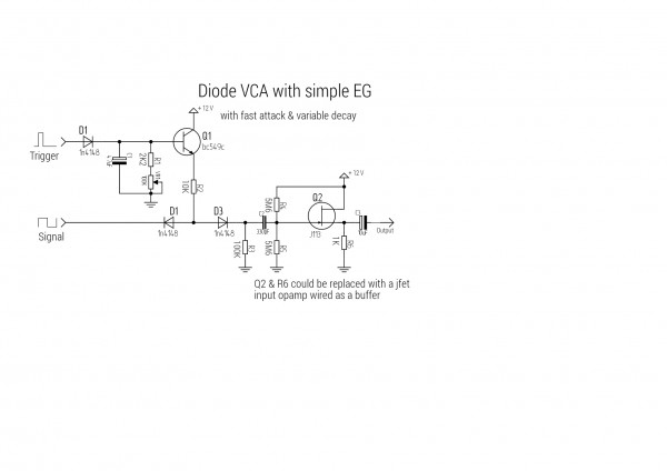
A few points about the 2-diode VCA and simple EGs:
The VCA is intended to amplitude modulate digital waveforms; the outputs of gates, inverters, counters, etc. There are those (you know who you are,) who claim it can handle a.c. coupled non-digital signals, such as the output of a filter. I am skeptical.
The resistor between the 2 diodes affects the length of Decay/Release that can be obtained. 22k-47k is good in most cases, depending, of course, on the value of the E.G. cap and the maximum length of Decay/Release desired.
In some cases, the diode pointing to the right -- the output -- might not be needed. The output can be direct or capacitor-coupled. Amplification will almost always be needed. In a system with an active mixer -- that is, an op amp or other device with some gain -- this won't be a problem.
In the AR envelope, the Release pot requires a path to ground in order to be effective. To ensure that's always the case, it would be better if it were in parallel with the capacitor, as in the percussive envelope, eliminating one diode. (Sorry 'bout that.)
Large value capacitors need more time to fully charge (or discharge,) than small ones. (t=RC) If the gate or trigger is too short the cap won't get up to the full gate/trigger voltage before Decay/Release begins, thus reducing the output level of the 2-diode or, for that matter, any other type of VCA. This can be a bug or a feature, depending on one's outlook.
These simple EGs can can control one or two 2-diode VCAs. More than that and the Decay/Release time diminishes. Trying to drive an LED places additional resistance in parallel with the cap, which will also shorten the Decay/Release time. One way around both problems would be to buffer the EG voltage with a non-inverting op amp or transistor emitter follower.
In short, with simplistic circuits such as these, trade-offs must be made to obtain satisfactory results. The only way to find satisfying trade-offs is to experiment.
e-follow.gif
Description:
Filesize:
2.35 KB
Viewed:
35723 Time(s)
_________________ Revenge is a dish best served with a fork... to the eye
Joined: Mar 19, 2011 Posts: 13 Location: Rochester
Posted: Sun Apr 24, 2011 5:05 pm Post subject:
I've been using an incredibly simple VCA idea that came from the Nic Collins book. It's not a proper VCA by any means, but I've had good results using a 40106 oscillator to blink an LED pointed towards a photocell. Run the audio through the photocell and you have a quasi envelope generator/voltage controlled attenuator combo.
One step further is to run the oscillator into an inverter and get an LED/photocell combo blinking opposite the non-inverted LED. If you run the two stages in series you can get short percussive envelopes.
Here's a clip of the non-inverted "vca" cascaded into the inverted "vca". Sound source is a few voltage starved NAND gate oscillators.
That one is pretty old, but I wonder how to add a manual gate trigger button to the schematic.
I built the diode vca and the a/r envelope thing, it works great with a 4093 Nand LFO, I tried to connect the gate in with v+ but it didn't worked. The a/r pots have no function, the release time is always long, the attack does not work. Should I use a resistor, like in the picture?
yes D5 is not working with this layout, you get the full release time. I tried to put another resistor to ground, between R9 and the switch, and now it is working near perfect. But another Problem that I have with the vca is, that I can't really use the output signal for something else then direct audio. I mean I can't plug a filter afterwards or something. I tried a unity gain buffer behind the vca but that is not working. Maybe I have to try a gate from a cmos inverter or something.
You cannot post new topics in this forum You cannot reply to topics in this forum You cannot edit your posts in this forum You cannot delete your posts in this forum You cannot vote in polls in this forum You cannot attach files in this forum You can download files in this forum

 Forum index » DIY Hardware and Software » Lunettas - circuits inspired by Stanley Lunetta