| Author |
Message |
HexInverter

Joined: Aug 21, 2010
Posts: 338
Location: Canada
|
 Posted: Tue Jan 18, 2011 10:16 pm Post subject:
The Liquid High Hat - Back from the dead! [PCB's] Posted: Tue Jan 18, 2011 10:16 pm Post subject:
The Liquid High Hat - Back from the dead! [PCB's]
Subject description: An awesome tunable noise source/high hat for your modular |
  |
|
I am pleased to say that for those that missed out on the first couple of runs:
PCBs are back in stock! Woot! http://shop.hexinverter.net/product.php?id_product=11
http://www.hexinverter.net
!!!IMPORTANT!!! PLEASE NOTE!: On the board layout silk-screen/parts image, C2 is shown installed incorrectly. Please REVERSE the polarity of C2 from what is shown in the manual and diagrams as of 09/21/2011
Thanks to some members of the forum for pointing this out! This (or any) project would not be possible without the lovely community we have here.
IF YOU HAVE BOARD REV.3, YOU CAN IGNORE THIS AND INSTALL AS INDICATED ON THE PCB!
When I fix this error in the manual and all of the documents, I will remove this message!

The boards are single sided, tinned, non-solder masked professionally manufactured boards. They are on .064" copper clad. I would have gotten them solder masked, except then it makes it hard to cut the traces for the Bentley mods/any hacks you may want to do.
UPDATES (scroll down for original post):
August 29, 2011 - I have begun the board ordering process! They should be here in about a month...hopefully earlier 
August 28, 2011 - I will be initializing the board ordering process within the next couple of days. Boards are set to be ordered on Sept 1/2nd, and should arrive ~1 month later at which point I will begin to ask for payments!
August 14, 2011 - Mathias has confirmed that boards are functioning adequately! Run #2 is happening very soon, and will see some board changes/tweaks. Please PM or reply to HexInverter if you wish to secure a board for yourself! 
May 6, 2011 - Bentley mod instructions are now available in the new .PDF manual (scroll down to attachments to download) YAY!!!
April 27, 2011 Boards are finally here! Yay. Added payment information above this post!
April 26, 2011 - Uploaded the .PDF instruction manual to this post, as well as updated the Bill of Materials. There is a package waiting for me at the post office which I believe to be the boards! I will report back tomorrow! 
March 21, 2011 - Whew! Okay. Boards are ordered Sorry for the wait. They should be here in a month or so! Let's hope it's faster
March 1, 2011 - Added the top side component layout image, as well as Rosch's picture he took of the homebrew PCB's he received from me. (scroll down!) I still haven't fixed the parts list, since I am waiting on the resistor values from Rich. That will be done when the manual is done. Board order very soon!!!
February 17, 2011 - Board layout is finally done! Waiting on the cash to make the board order. HOMEBREW PCB's will be available starting this weekend! (Saturday, February 19, 2011) and are $15CAD each. Please message me if you are interested in these non drilled PCB's, so I know how many to make! Me and Rich are working on the manual/assembly/instructions while waiting for the funds to order boards.
February 11, 2011 - Plans have changed a bit, to have boards produced by a board house due to larger order volume than expected. They will be $17 each. Those that would like to drill their own can get boards made by me for $15 each, that are NOT drilled. (view this post for the detailed information about this change: http://electro-music.com/forum/post-322233.html#322233 )
February 7th, 2011 - Board has been tested and adjusted by Rich! Final board design is in development.
January 28th, 2011 - Prototype board has been received by Rich for testing and adjustments.
January 22nd, 2011 - Prototype board is done! (Picture below!) Rich should have it in his hot little hands for testing before the end of next week! (That's not to say he will have it tested by then, just that he will have it!  ) )
January 20th, 2011 - Bill of Materials posted so you know what parts you'll need ahead of time!
Quick Info for those that don't want to read my novel below:
What? A voltage controlled noise source/hi-hat voice. There is NO AR/VCA on board, but it makes all sorts of awesome sounds.
There are also a number of awesome modifications that are able to be performed on the module, increasing the sonic possibilities by a large scale.
Who? Designed by Ryk John Miller Thekreator, a few years back. The original board run never happened, so I am taking over with his permission to make home etched boards for everyone that wants one.
How long? Not too long before the layout is sent off for full production![/b]
Original Post:
Some of you may recall the development progress of a rather great sounding high hat / tunable noise module designed by Rykhaard / Rich / Ryk over in this old, old, original thread here:
http://electro-music.com/forum/topic-27756.html&postorder=asc
Well, for whatever reasoning, the PCB's never ended up getting made! What a shame...
Well, I have come to fix that with my rather nice home made PCB's! The Liquid High Hat will be produced after all! I have a really nice method of producing single sided home etched PCB's. Better than most you are used to, I am sure. I am also a broke student having trouble finding a part time job, so it is mutually beneficial! 
This is fully approved by Rich himself, by the way! No silly shenanigans here!
They will be mostly single sided, and completely hand routed, with some wire jumpers. ALL jumpers will be 1 dimensional and through hole installed (what I mean is: no hook up wire traveling silly distances in a rats nest across the board or anything like that - all are straight jumpers, no curved or slanted.)
They will be pre-drilled by me in my lab and mailed out to you as per your order.
There is NO silk screening, as I unfortunately don't have the tools for that. I wish I could offer it! Sorry. The bottom copper layout has lettering that reads properly FROM the top side of the board, "pseudo-silkscreening" I guess
I can't put a price on the boards yet, but rest assured they will not be horribly expensive or anything like that.
The plus to ME doing it instead of a board house is that once the design is done, production is MUCH faster!
Drop me a response here or a PM if you think you might be interested in this, so I have rough figure of how many I will need to fabricate!
Cheers!
-Hex
Bill of Materials (subject to change!):
10nF Film Capacitor 4
.1uF Ceramic Capacitor 11
10uF Electrolytic Capacitor 2
TL074 Quad Op Amp 1
TL072 Dual Op Amp 1
CD4046 Phase Locked Loop 2
CD40106 Hex Inverter 1
CD4070 Quad XOR Gate 1
1N914 Diode 2
22ohm Resistor 2
100k Resistor 21
220k Resistor 3
1k Resistor 6
10k Resistor 4
1M Resistor 2
100k Potentiometer 3
1M Potentiometer 6
1/4” Jack (or whatever you use) 6
Hook up wire - Pads are drilled to accept up to 22AWG!
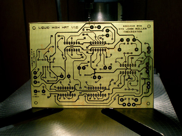
This is how the homebrew PCB's turned out, and how Rosch received his. Preeetty

| Description: |
|
| Filesize: |
199.62 KB |
| Viewed: |
297 Time(s) |
| This image has been reduced to fit the page. Click on it to enlarge. |

|
| Description: |
| The latest and greatest assembly guide for the Liquid High Hat v1.1, including instructions for making yourself a Bentley-modded version! |
|

Download (listen) |
| Filename: |
lhh1.1_assemblyguideREV2.pdf |
| Filesize: |
5.16 MB |
| Downloaded: |
1283 Time(s) |
Last edited by HexInverter on Tue Jul 03, 2012 12:05 pm; edited 34 times in total |
|
|
Back to top
|
|
 |
andrewF

Joined: Dec 29, 2006
Posts: 1176
Location: australia
Audio files: 4
|
| Posted: Wed Jan 19, 2011 4:04 am Post subject:
|
|
|
They look really good, especially in comparison to my home-etching efforts.
Are you sure you really want to drill out so many pcbs? that will get very tedious.
for a larger run, it may be simpler & cheaper to get the boards manufactured.
I get prototypes done at futurlec without soldermask or screenprint - its very cheap and 'only' takes 1 month
ie ten boards at 3" by 2", single-sided, tinned, no soldermask or screen print is $42.
40 boards is $123, so around $3 each.
Might be worth it to compare to the cost of materials, drillbits, chemicals, etc plus X number of hours to etch, cut and drill the boards.
For me futurlec wins, I have enough backlog that a month's wait is no problem.
Hope this doesn't put you off or seem too negative, what you are doing is fantastic, just offering an alternative......the thought of all that drilling makes me  |
|
|
Back to top
|
|
|
HexInverter
Joined: Aug 21, 2010
Posts: 338
Location: Canada
|
| Posted: Wed Jan 19, 2011 7:17 am Post subject:
|
|
|
| andrewF wrote: | They look really good, especially in comparison to my home-etching efforts.
Are you sure you really want to drill out so many pcbs? that will get very tedious.
for a larger run, it may be simpler & cheaper to get the boards manufactured.
I get prototypes done at futurlec without soldermask or screenprint - its very cheap and 'only' takes 1 month
ie ten boards at 3" by 2", single-sided, tinned, no soldermask or screen print is $42.
40 boards is $123, so around $3 each.
Might be worth it to compare to the cost of materials, drillbits, chemicals, etc plus X number of hours to etch, cut and drill the boards.
For me futurlec wins, I have enough backlog that a month's wait is no problem.
Hope this doesn't put you off or seem too negative, what you are doing is fantastic, just offering an alternative......the thought of all that drilling makes me |
You bring up a very good point!
And those are some nice prices.
However, I have done bulk loads of drilling before though, so no worries. My patience is quite high...usually. hehe. It helps to have a half decent drill press and stool to sit on. (and nice safety glasses mind you )
Perhaps a second run of other boards could be done if there's a huge over demand...but as it stands unless I asked for money in advance, I could not even muster up the cash to do a board order. I really meant it that I'm broke I just happen to have a big pile of PCB making materials, and shipping envelopes here stocked up (I also sell stuff on eBay, so have the shipping materials for that)
Thanks for the response! |
|
|
Back to top
|
|
|
loydb
Joined: Feb 04, 2010
Posts: 393
Location: Providence, RI
|
|
|
Back to top
|
|
|
emdot_ambient
Joined: Nov 22, 2009
Posts: 667
Location: Frederick, MD
|
| Posted: Wed Jan 19, 2011 11:03 am Post subject:
|
|
|
Is there a BOM available? Just wondering if there are any hard to source parts for this.
I'm sure I'd be in for 1, possibly 2, depending on the final price. |
|
|
Back to top
|
|
|
rosch

Joined: Oct 03, 2009
Posts: 164
Location: germany
|
| Posted: Wed Jan 19, 2011 12:01 pm Post subject:
|
|
|
cool service! and thanks for the link to here.
i'm in for at least 2, also depending on the price.
your boards look really good btw |
|
|
Back to top
|
|
|
ericcoleridge

Joined: Jan 16, 2007
Posts: 889
Location: NYC
|
| Posted: Wed Jan 19, 2011 1:05 pm Post subject:
|
|
|
| andrewF wrote: |
I get prototypes done at futurlec without soldermask or screenprint - its very cheap and 'only' takes 1 month
ie ten boards at 3" by 2", single-sided, tinned, no soldermask or screen print is $42.
40 boards is $123, so around $3 each.
|
andrew-- what file format does Futurlec ask for-- what do you use to layout your PCBs? I had no idea that this was so inexpensive. |
|
|
Back to top
|
|
|
HexInverter
Joined: Aug 21, 2010
Posts: 338
Location: Canada
|
| Posted: Wed Jan 19, 2011 3:16 pm Post subject:
|
|
|
| emdot_ambient wrote: | Is there a BOM available? Just wondering if there are any hard to source parts for this.
I'm sure I'd be in for 1, possibly 2, depending on the final price. |
There WILL be a BOM, and a layout.
I can tell you off the top of my head that it is not hard to find the parts...a couple op-amps and CMOS 4000 series chips! (other than the usual caps, resistors, pots, etc...)
No hard to find parts, if that's what you mean.
Thanks for the responses people!
@ Eric - Looking at Futurlec's website, it seems they accept boards in most of the common PCB CAD program formats. |
|
|
Back to top
|
|
|
Danno Gee Ray
Joined: Sep 25, 2005
Posts: 1351
Location: Telford, PA USA
|
| Posted: Wed Jan 19, 2011 3:29 pm Post subject:
|
|
|
| As previously insicated on the original thread, I'm in for 1. |
|
|
Back to top
|
|
|
andrewF
Joined: Dec 29, 2006
Posts: 1176
Location: australia
Audio files: 4
|
| Posted: Wed Jan 19, 2011 5:07 pm Post subject:
|
|
|
| ericcoleridge wrote: |
andrew-- what file format does Futurlec ask for-- what do you use to layout your PCBs? I had no idea that this was so inexpensive. |
this is another good point with futurlec
they take altium, eagle, expresspcb, gerber, orcad, pad2pad, pcb-wizard, protel and sprint-layout.
I now use expressPCB (free), used to use Altium ($). you just send in the file from whatever program you used.
It always takes 1 month (+/- a day or two) to get the boards.
make sure you state you want 'standard delivery' otherwise they will try to send by fedex for $40 or so (and it will still take a month).
You can use paypal (just tell them you want to)
here are some TS22 tube filterbanks and ts23 tube dual VCOs I had done.
The TS22s were soldermasked by mistake
The tracks on here are very thick, which i prefer for tube ccts.

back to discussion of HexInverters excellent home etched boards! |
|
|
Back to top
|
|
|
HexInverter
Joined: Aug 21, 2010
Posts: 338
Location: Canada
|
| Posted: Wed Jan 19, 2011 5:19 pm Post subject:
|
|
|
| andrewF wrote: | | ericcoleridge wrote: |
andrew-- what file format does Futurlec ask for-- what do you use to layout your PCBs? I had no idea that this was so inexpensive. |
this is another good point with futurlec
they take altium, eagle, expresspcb, gerber, orcad, pad2pad, pcb-wizard, protel and sprint-layout.
I now use expressPCB (free), used to use Altium ($). you just send in the file from whatever program you used.
It always takes 1 month (+/- a day or two) to get the boards.
make sure you state you want 'standard delivery' otherwise they will try to send by fedex for $40 or so (and it will still take a month).
You can use paypal (just tell them you want to)
here are some TS22 tube filterbanks and ts23 tube dual VCOs I had done.
The TS22s were soldermasked by mistake
The tracks on here are very thick, which i prefer for tube ccts.
back to discussion of HexInverters excellent home etched boards! |
Very nice! Thanks for letting us in on this!
As an update: board design is in progress! I expect to have the first prototype board etched by the end of this weekend at the latest...then it will be mailed out to Rich who will give it a test for us, and later, the go ahead for me to go nuts making them! |
|
|
Back to top
|
|
|
HexInverter
Joined: Aug 21, 2010
Posts: 338
Location: Canada
|
|
|
Back to top
|
|
|
rosch
Joined: Oct 03, 2009
Posts: 164
Location: germany
|
| Posted: Thu Jan 20, 2011 8:42 pm Post subject:
|
|
|
| HexInverter wrote: | | ...just to know I'm not lying or anything. |
looks great! |
|
|
Back to top
|
|
|
LektroiD

Joined: Aug 23, 2008
Posts: 1019
Location: Scottish Borders
Audio files: 2
G2 patch files: 2
|
Posted: Thu Jan 20, 2011 9:47 pm Post subject:
 |
|
|
Count me in for Two of these babies (one open and one closed)!
_________________
LektroiD |
|
|
Back to top
|
|
|
Dragon's Lair

Joined: Dec 29, 2006
Posts: 205
Location: Hope BC, Canada
Audio files: 1
|
| Posted: Thu Jan 20, 2011 9:49 pm Post subject:
|
|
|
Nice layout 
One suggestion, you should change the pads for the pots and jacks to the standard .1 spacing, so people have the option of using headers. |
|
|
Back to top
|
|
|
HexInverter
Joined: Aug 21, 2010
Posts: 338
Location: Canada
|
| Posted: Fri Jan 21, 2011 6:42 am Post subject:
|
|
|
| Dragon's Lair wrote: | Nice layout
One suggestion, you should change the pads for the pots and jacks to the standard .1 spacing, so people have the option of using headers. |
The thought crossed my mind!
And if anyone else desperately wants headers, please chime in...but the way I see it is:
Unfortunately not everyone uses headers, and using headers would mean a smaller pad size than I am using here, which would mean a smaller drill size - which would mean less sizes of wire would be able to fit in the board.
Personally, I use salvaged wire, which is very rarely the small size that would fit into a header pin's hole. I know not everyone uses the same gauge wire.
Everyone has wire and can use it; not everyone has headers and can use them...so I am appealing to the "fail safe"/"majority" crowd so nobody is left in the dark functionality wise.
The problem lies in the fact that the header pin's pads are fairly closely spaced together. I can't use a larger drill than an IC leg because of the risk of human error making the pad useless due to it's small size. If I were to do the logical thing and increase the size (which my Eagle design rules do automatically anyways), the pads come very close to intersecting eachother...which is fine, except for home etching. There is a rather large possibility that when making a batch of boards, a handful of them will have errors due to the header pins pad proximity. I don't want that...
Also, it would require more jumper wires if I use header pins since I cannot route wires between pins like I have here.
So, in short - if it were a pro board run that can do much finer traces - no problem! But since I am etching them, unless there is a huge amount of people wanting headers instead of wire pads, I am going to leave it as is. |
|
|
Back to top
|
|
|
HexInverter
Joined: Aug 21, 2010
Posts: 338
Location: Canada
|
| Posted: Fri Jan 21, 2011 7:50 am Post subject:
|
|
|
| LektroiD wrote: | | Count me in for Two of these babies (one open and one closed)! |
Sounds good! I will put you down for two
Thanks, Rosch!
Why can I not figure out how to multi quote on this forum? Can someone explain to me how to multi quote? Man I feel like an idiot... |
|
|
Back to top
|
|
|
LektroiD
Joined: Aug 23, 2008
Posts: 1019
Location: Scottish Borders
Audio files: 2
G2 patch files: 2
|
| Posted: Fri Jan 21, 2011 10:48 am Post subject:
|
|
|
deleted OT post
Last edited by LektroiD on Fri Jan 21, 2011 2:03 pm; edited 2 times in total |
|
|
Back to top
|
|
|
magman
Joined: Feb 04, 2009
Posts: 363
Location: Liverpool, UK
|
| Posted: Fri Jan 21, 2011 12:11 pm Post subject:
|
|
|
| HexInverter wrote: | The problem lies in the fact that the header pin's pads are fairly closely spaced together. I can't use a larger drill than an IC leg because of the risk of human error making the pad useless due to it's small size. If I were to do the logical thing and increase the size (which my Eagle design rules do automatically anyways), the pads come very close to intersecting eachother...which is fine, except for home etching. There is a rather large possibility that when making a batch of boards, a handful of them will have errors due to the header pins pad proximity. I don't want that...
|
The trick I've seen other people use on their boards is to actually use 5 pads and just short the outer 2 on each side. If you use IC style pads, you've also got a bit of latitude for drilling out the holes slightly larger. For an example, have a look at look at the pads on the Cat Girl CGS59 Programmer-Sequencer.
I have an ulterior motive for this suggestion as well, I prefer to use BI/TT conductive Plastic pots, like these:
BI/TT Pots at Rapid
Which have a 0.1" pin spacing, which is also used by Bourns and Vishay for some of their better quality pots. But like someone has already mentioned, you can also use them for connectors to the pots if required.
Might still be interested in a couple of these boards myself, though.
Regards
Magman |
|
|
Back to top
|
|
|
HexInverter
Joined: Aug 21, 2010
Posts: 338
Location: Canada
|
| Posted: Fri Jan 21, 2011 1:50 pm Post subject:
|
|
|
| magman wrote: | | HexInverter wrote: | The problem lies in the fact that the header pin's pads are fairly closely spaced together. I can't use a larger drill than an IC leg because of the risk of human error making the pad useless due to it's small size. If I were to do the logical thing and increase the size (which my Eagle design rules do automatically anyways), the pads come very close to intersecting eachother...which is fine, except for home etching. There is a rather large possibility that when making a batch of boards, a handful of them will have errors due to the header pins pad proximity. I don't want that...
|
The trick I've seen other people use on their boards is to actually use 5 pads and just short the outer 2 on each side. If you use IC style pads, you've also got a bit of latitude for drilling out the holes slightly larger. For an example, have a look at look at the pads on the Cat Girl CGS59 Programmer-Sequencer.
I have an ulterior motive for this suggestion as well, I prefer to use BI/TT conductive Plastic pots, like these:
BI/TT Pots at Rapid
Which have a 0.1" pin spacing, which is also used by Bourns and Vishay for some of their better quality pots. But like someone has already mentioned, you can also use them for connectors to the pots if required.
Might still be interested in a couple of these boards myself, though.
Regards
Magman |
Interesting idea, thanks for the tip.
If you take a look at the board layout though, I have not designed the board to have all of the pots directly at the edge of the board, so there is really no way you could use those nice right angle potentiometers anyways.
Of course in a multilayer board I could do that - but not only would it make the boards much larger, it would add a lot more jumpers to the mix.
I did my best to keep the layout of pots and jacks as logical as possible, but it's still not perfectly ideal. |
|
|
Back to top
|
|
|
rosch
Joined: Oct 03, 2009
Posts: 164
Location: germany
|
| Posted: Fri Jan 21, 2011 7:28 pm Post subject:
|
|
|
| did you actually include the features fonik had suggested earlier in the other thread? |
|
|
Back to top
|
|
|
HexInverter
Joined: Aug 21, 2010
Posts: 338
Location: Canada
|
| Posted: Fri Jan 21, 2011 7:36 pm Post subject:
|
|
|
| rosch wrote: | | did you actually include the features fonik had suggested earlier in the other thread? |
What an excellent question! I had meant to mention that in the original post, but forgot...silly me.
The answer is, no. I decided to keep it simple, and the "general" consensus was to just use an external EG/VCA if wanted. I can't please everyone 
Also, time, and resources was another matter. I only have a certain amount of time to produce the boards before I am going to be mad busy with other stuff, so using the already available drawings without further complicating the matter was the best choice.
That being said, I'd say it's going pretty well! The first prototype board is ready to be etched already! |
|
|
Back to top
|
|
|
rosch
Joined: Oct 03, 2009
Posts: 164
Location: germany
|
| Posted: Fri Jan 21, 2011 7:42 pm Post subject:
|
|
|
| HexInverter wrote: | | The first prototype board is ready to be etched already! |
cool! |
|
|
Back to top
|
|
|
HexInverter
Joined: Aug 21, 2010
Posts: 338
Location: Canada
|
|
|
Back to top
|
|
|
telbonic
Joined: Jan 08, 2010
Posts: 39
Location: uk
|
| Posted: Sun Jan 23, 2011 9:32 am Post subject:
|
|
|
It's all looking good - I get that smearing once in a while, I think some of the dyes in the ink seperate out and bond to the board somehow - it generally happens when I'm being light on the acetone.
Will it be possible for those of us with all the gear to etch our own boards from the original artwork rather than ordering boards? I'm in the UK, it's a bit quicker to roll my own as it were |
|
|
Back to top
|
|
|
|

 Forum index » DIY Hardware and Software