| Front Page | Radio | Media | Forum | Wiki | Links |

and electronic music
|
|
Dedicated to
experimental electro-acoustic and electronic music |
|
|
|
|
|||||||||
 Forum index » DIY Hardware and Software » Lunettas - circuits inspired by Stanley Lunetta Forum index » DIY Hardware and Software » Lunettas - circuits inspired by Stanley Lunetta |
|
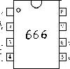
LDR VCA type thing
|
 
|
Moderators: mosc
Page 1 of 1 [10 Posts] |
View unread posts View new posts in the last week Mark the topic unread :: View previous topic :: View next topic |
| Author | Message | |||||||||||||||||||
|---|---|---|---|---|---|---|---|---|---|---|---|---|---|---|---|---|---|---|---|---|
mike page
 Joined: Sep 26, 2016 Posts: 134 Location: norwich, uk |
|
|||||||||||||||||||
|
|
||||||||||||||||||||
Grumble
 Joined: Nov 23, 2015 Posts: 1310 Location: Netherlands Audio files: 30 |
|
|||||||||||||||||||
|
|
||||||||||||||||||||
|
mike page
Joined: Sep 26, 2016 Posts: 134 Location: norwich, uk |
|
|||||||||||||||||||
|
|
||||||||||||||||||||
|
Grumble
Joined: Nov 23, 2015 Posts: 1310 Location: Netherlands Audio files: 30 |
|
|||||||||||||||||||
|
|
||||||||||||||||||||
PHOBoS
 Joined: Jan 14, 2010 Posts: 5795 Location: Moon Base Audio files: 709 |
|
|||||||||||||||||||
|
|
||||||||||||||||||||
|
mike page
Joined: Sep 26, 2016 Posts: 134 Location: norwich, uk |
|
|||||||||||||||||||
|
|
||||||||||||||||||||
|
mike page
Joined: Sep 26, 2016 Posts: 134 Location: norwich, uk |
|
|||||||||||||||||||
|
|
||||||||||||||||||||
|
mike page
Joined: Sep 26, 2016 Posts: 134 Location: norwich, uk |
|
|||||||||||||||||||
|
|
||||||||||||||||||||
|
PHOBoS
Joined: Jan 14, 2010 Posts: 5795 Location: Moon Base Audio files: 709 |
|
|||||||||||||||||||
|
|
||||||||||||||||||||
|
StasV
Joined: Jul 21, 2017 Posts: 1 Location: Slovenia, Ljubljana |
|
|||||||||||||||||||
|
|
||||||||||||||||||||
|
|
Moderators: mosc
Page 1 of 1 [10 Posts] |
View unread posts View new posts in the last week Mark the topic unread :: View previous topic :: View next topic |
|
Forum index » DIY Hardware and Software » Lunettas - circuits inspired by Stanley Lunetta |
|
You cannot post new topics in this forum You cannot reply to topics in this forum You cannot edit your posts in this forum You cannot delete your posts in this forum You cannot vote in polls in this forum You cannot attach files in this forum You can download files in this forum |