| Author |
Message |
Uncle Krunkus
Moderator

Joined: Jul 11, 2005
Posts: 4761
Location: Sydney, Australia
Audio files: 52
G2 patch files: 1
|
 Posted: Mon Mar 24, 2008 4:31 am Post subject:
Octave switcher problem on ASM-2 Posted: Mon Mar 24, 2008 4:31 am Post subject:
Octave switcher problem on ASM-2
Subject description: Extra mods for my VCOs needed |
  |
|
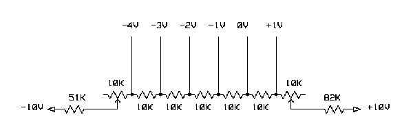
I've been trying to iron out some problems with my ASM-2 Sorcerer. Most notably, not being able to get my octave switcher to work properly. This basically means that I can't get it in tune and have any confidence in how CVs actually work.
I've unplugged all other CV ins from the VCO, and tested what is coming out of the octave switcher. For the six different positions I get -4, -3, -2, -1, 0, +1V. But as soon as I plug it into one of the CV ins, it changes. For example the last three values are -.67, 0, +.67V Now I find it really suspicious that the 1V ranges get pulled back to 2/3V. Could there be something about the VCO which is letting it be "loaded" in some way?
I'll attach a schem of the VCO summer section in case that helps.
This is really weird, I thought I'd sorted all this stuff out, but obviously something still hasn't set right in my brain! 
Any help or advice would be greatly appreciated. I feel really stuck and lost and incompetent. 
| Description: |
|

Download (listen) |
| Filename: |
vco1-summer-asm2-cct.pdf |
| Filesize: |
21.15 KB |
| Downloaded: |
571 Time(s) |
_________________
What makes a space ours, is what we put there, and what we do there.
Last edited by Uncle Krunkus on Tue Apr 01, 2008 12:39 am; edited 1 time in total |
|
|
Back to top
|
|
 |
frijitz
Joined: May 04, 2007
Posts: 1734
Location: NM USA
Audio files: 54
|
| Posted: Mon Mar 24, 2008 5:52 am Post subject:
Re: Octave switcher problem on ASM-2 |
|
|
| Uncle Krunkus wrote: | | Could there be something about the VCO which is letting it be "loaded" in some way? |
The VCO will load your octave switcher some, depending on the switcher's output impedance. Would need to see that schematic to answer the question.

Ian |
|
|
Back to top
|
|
|
Uncle Krunkus
Moderator
Joined: Jul 11, 2005
Posts: 4761
Location: Sydney, Australia
Audio files: 52
G2 patch files: 1
|
|
|
Back to top
|
|
|
frijitz
Joined: May 04, 2007
Posts: 1734
Location: NM USA
Audio files: 54
|
| Posted: Mon Mar 24, 2008 9:38 am Post subject:
|
|
|
Yeah, that's a high impedance circuit. You need to buffer it before it goes to the VCO. What is happening is that the output impedance is adding to the VCO input resistor, so the input summer is putting out less than it should.
Ian |
|
|
Back to top
|
|
|
Uncle Krunkus
Moderator
Joined: Jul 11, 2005
Posts: 4761
Location: Sydney, Australia
Audio files: 52
G2 patch files: 1
|
| Posted: Mon Mar 24, 2008 1:47 pm Post subject:
|
|
|
Can the switcher be re-designed so it doesn't need a buffer? ie: can I make the same thing with lower impedance? I mean, some coarse tune pots are just that, a pot yeah? You can find a number of octaves on one of those. Does the 1V/Oct still work through a 100K summing resistor regardless of what might be hanging off another summing resistor? Man,..... what a nightmare! How come nobody else has been hit with this?
_________________
What makes a space ours, is what we put there, and what we do there. |
|
|
Back to top
|
|
|
Clack

Joined: Aug 08, 2005
Posts: 438
Location: Walthamstow - london
Audio files: 5
G2 patch files: 1
|
|
|
Back to top
|
|
|
Uncle Krunkus
Moderator
Joined: Jul 11, 2005
Posts: 4761
Location: Sydney, Australia
Audio files: 52
G2 patch files: 1
|
|
|
Back to top
|
|
|
Uncle Krunkus
Moderator
Joined: Jul 11, 2005
Posts: 4761
Location: Sydney, Australia
Audio files: 52
G2 patch files: 1
|
| Posted: Mon Mar 24, 2008 2:09 pm Post subject:
|
|
|
Jesus - H - Christ - Mr - Clack! Where did you find that?
I think the world has moved on a long way since I got my ASM-2 docs!
This indeed does exactly what Ian is talking about, and would allow plugging in to any 100K summer input, I think.
I still wonder whether the 1M5 input is the short term solution though. It would settle a few doubts rattling around in my head. 
_________________
What makes a space ours, is what we put there, and what we do there. |
|
|
Back to top
|
|
|
blue hell
Site Admin

Joined: Apr 03, 2004
Posts: 24493
Location: The Netherlands, Enschede
Audio files: 298
G2 patch files: 320
|
| Posted: Mon Mar 24, 2008 2:43 pm Post subject:
|
|
|
| Uncle Krunkus wrote: | | I still wonder whether the 1M5 input is the short term solution though. It would settle a few doubts rattling around in my head. |
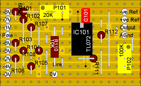
When the 1M5 goes to the same summing input as the 100k inputs it has a different sensitivity, so you would have to rescale the octave voltages ... no way out but to build the buffer I'm afraid
_________________
Jan
also .. could someone please turn down the thermostat a bit.
 |
|
|
Back to top
|
|
|
frijitz
Joined: May 04, 2007
Posts: 1734
Location: NM USA
Audio files: 54
|
| Posted: Mon Mar 24, 2008 2:54 pm Post subject:
|
|
|
| Uncle Krunkus wrote: | | I mean, some coarse tune pots are just that, a pot yeah? You can find a number of octaves on one of those. |
Sure you can.
But they are not at convenient resistance values. In other words, you *could* design a high impedance octave switcher, but you would have to *simultaneously* calculate all the *different* resistor values. And trim them all.
That's why they invented buffers.
Ian |
|
|
Back to top
|
|
|
Uncle Krunkus
Moderator
Joined: Jul 11, 2005
Posts: 4761
Location: Sydney, Australia
Audio files: 52
G2 patch files: 1
|
| Posted: Mon Mar 24, 2008 4:51 pm Post subject:
|
|
|
Okay, okay, I'm sold. I'll build the buffers onto the back of my octave switchers.
Now I assume that this will be the case for any octave switcher right?
I mean I'm not being singled out for the "Now go to your room and build some buffers!" treatment am I? 
BTW I'm gonna make them 8 position switchers while I'm at it. So there! 
BTBTW Anyone want the stripboard layouts when I'm done? 
_________________
What makes a space ours, is what we put there, and what we do there. |
|
|
Back to top
|
|
|
blue hell
Site Admin
Joined: Apr 03, 2004
Posts: 24493
Location: The Netherlands, Enschede
Audio files: 298
G2 patch files: 320
|
| Posted: Mon Mar 24, 2008 4:54 pm Post subject:
|
|
|
| Uncle Krunkus wrote: | | I mean I'm not being singled out for the "Now go to your room and build some buffers!" treatment am I? |
Depends .. others might be tone deaf ... that would work just as well
_________________
Jan
also .. could someone please turn down the thermostat a bit.
|
|
|
Back to top
|
|
|
Clack
Joined: Aug 08, 2005
Posts: 438
Location: Walthamstow - london
Audio files: 5
G2 patch files: 1
|
| Posted: Mon Mar 24, 2008 4:58 pm Post subject:
|
|
|
| Quote: | | Jesus - H - Christ - Mr - Clack! Where did you find that? |
http://www.elby-designs.com/synth-modules/octave/octave.htm its in the genie section - seems he may have offered the pcb for a while ( which looks very tidy ) - I never saw it, still on my way to finishing mine (btw does the document on the CD tell you what value pots go fo what controls? there is no info on this on the site. I lost my CD ).
now go to your room and finish your synthwork!
_________________
Clacktronics.co.uk |
|
|
Back to top
|
|
|
Uncle Krunkus
Moderator
Joined: Jul 11, 2005
Posts: 4761
Location: Sydney, Australia
Audio files: 52
G2 patch files: 1
|
| Posted: Mon Mar 24, 2008 5:58 pm Post subject:
|
|
|
| Blue Hell wrote: | | Uncle Krunkus wrote: | | I mean I'm not being singled out for the "Now go to your room and build some buffers!" treatment am I? |
Depends .. others might be tone deaf ... that would work just as well |
Sometimes I think being tone deaf could be a blessing in disguise!
A very underated source of ignorance/bliss.
_________________
What makes a space ours, is what we put there, and what we do there. |
|
|
Back to top
|
|
|
Uncle Krunkus
Moderator
Joined: Jul 11, 2005
Posts: 4761
Location: Sydney, Australia
Audio files: 52
G2 patch files: 1
|
| Posted: Mon Mar 24, 2008 6:12 pm Post subject:
|
|
|
| Mr Clack wrote: | | Quote: | | Jesus - H - Christ - Mr - Clack! Where did you find that? |
http://www.elby-designs.com/synth-modules/octave/octave.htm its in the genie section - seems he may have offered the pcb for a while ( which looks very tidy ) - I never saw it, still on my way to finishing mine (btw does the document on the CD tell you what value pots go fo what controls? there is no info on this on the site. I lost my CD ).
now go to your room and finish your synthwork! |
Yes, I know where you got it! It was a rhetorical question! "Why I outta!"
Anyway, I've had to work out alot of it myself, and I'm sure there are plenty of things I could put some extra work into. It is a big project, and improving it could take some time. I'm not sure where I got the values for my pots, but if you need any specifics, just ask.
Oh, look, I just found this. Doesn't include everything. There are other pots I've included which aren't listed. Like levels for the ring mod inputs etc. Have you worked out a front panel yet? I can send you a pic of mine if you want some inspiration.
All up, it is a really nice sounding synth, and I know there is more in there for me to wring out of the basic design.
| Description: |
|
Download (listen) |
| Filename: |
asmx-appendix-b.pdf |
| Filesize: |
554.79 KB |
| Downloaded: |
717 Time(s) |
_________________
What makes a space ours, is what we put there, and what we do there. |
|
|
Back to top
|
|
|
Uncle Krunkus
Moderator
Joined: Jul 11, 2005
Posts: 4761
Location: Sydney, Australia
Audio files: 52
G2 patch files: 1
|
| Posted: Mon Mar 24, 2008 6:17 pm Post subject:
|
|
|
One more question,
Can I run the buffer op-amps off the reference +/-10V which is already going to the old switchers? I only want -5 to +2 so I assume it should be fine.
_________________
What makes a space ours, is what we put there, and what we do there. |
|
|
Back to top
|
|
|
blue hell
Site Admin
Joined: Apr 03, 2004
Posts: 24493
Location: The Netherlands, Enschede
Audio files: 298
G2 patch files: 320
|
| Posted: Mon Mar 24, 2008 6:27 pm Post subject:
|
|
|
| Uncle Krunkus wrote: | One more question,
Can I run the buffer op-amps off the reference +/-10V which is already going to the old switchers? I only want -5 to +2 so I assume it should be fine. |
Probably, but are you sure you want to do that? feeding a work horse from a reference voltage I mean ... You'd get away with it I guess, but ... erm ... anyway, I'm biting my tongue
_________________
Jan
also .. could someone please turn down the thermostat a bit.
|
|
|
Back to top
|
|
|
etaoin

Joined: Jun 30, 2005
Posts: 761
Location: Utrecht, NL
|
|
|
Back to top
|
|
|
Uncle Krunkus
Moderator
Joined: Jul 11, 2005
Posts: 4761
Location: Sydney, Australia
Audio files: 52
G2 patch files: 1
|
| Posted: Thu Mar 27, 2008 7:57 am Post subject:
|
|
|
In reply to both Jan and Etaoin (how do you pronounce that?)
I understand your concerns and advice, but this octave switcher is for a self contained ASM-2. It's not a modular. It has it's own PSU, and dedicated reference, so I'm not that concerned with running clean power to the "workhorse" if you know what I mean. And this octave switcher, or rather two of them, will hang off the back of the actual rotary switch. It's a special feature, not a separate module. Small, simple, accurate, that's the need.
And with that I submit my solution: -
It's designed to solder directly onto a 12 position rotary. Across the position 1 (-8V), Pole, and position 6 (-3V) pins. I actually went for the full 9 position version, which means 10 connections to the switch. All but the aforemention 3 must be made with solid strand wire.
| Description: |
|
| Filesize: |
19.09 KB |
| Viewed: |
17373 Time(s) |
|
| Description: |
|
| Filesize: |
14.11 KB |
| Viewed: |
17373 Time(s) |
|
_________________
What makes a space ours, is what we put there, and what we do there.
Last edited by Uncle Krunkus on Sun Apr 13, 2008 9:40 am; edited 1 time in total |
|
|
Back to top
|
|
|
Uncle Krunkus
Moderator
Joined: Jul 11, 2005
Posts: 4761
Location: Sydney, Australia
Audio files: 52
G2 patch files: 1
|
| Posted: Mon Mar 31, 2008 6:00 pm Post subject:
|
|
|
Well,
while I was exploring the process of adding the octave switcher buffers, I went back and had a look at the Elby site. I downloaded the latest set of schems for the ASM-2 and I've created a whole new load of work for myself.
It seems my PCB (which was really a prototype (Laurie actually told me to wait for a tested version, and I said I'd take my chances, it has taught me alot!)) doesn't have sync buffers! No wonder I've always found the sync to sound a bit, well,... not there!
I also found 4 resistors in each VCO which have had their values modified. I've only checked the VCOs so far!
So my job at the moment is to get the VCOs up to speed. They actually sounded quite good before, so I'm expecting them to sound even better.
I have to put the stripboard octave switcher with buffer on the back of the switch, build a second stripboard with the sync buffer on it which will plug into the VCO with risers, and change the value of 4 resistors. And all of that on the other VCO as well!
I'll take some photos when I'm done.
_________________
What makes a space ours, is what we put there, and what we do there. |
|
|
Back to top
|
|
|
Uncle Krunkus
Moderator
Joined: Jul 11, 2005
Posts: 4761
Location: Sydney, Australia
Audio files: 52
G2 patch files: 1
|
|
|
Back to top
|
|
|
Uncle Krunkus
Moderator
Joined: Jul 11, 2005
Posts: 4761
Location: Sydney, Australia
Audio files: 52
G2 patch files: 1
|
| Posted: Sat Apr 12, 2008 7:54 am Post subject:
|
|
|
Do not build this octave switcher.
It's been trolled to output the opposite voltage.
I should have known, I was close to asking, isn't that an inverting buffer followed by a non-inverting buffer? Doesn't that mean the output will be upside down?
Anyway, I'm gonna replace the -10V into the divider with +10V, and it should be fine.
_________________
What makes a space ours, is what we put there, and what we do there.
Last edited by Uncle Krunkus on Sat Apr 12, 2008 4:03 pm; edited 1 time in total |
|
|
Back to top
|
|
|
blue hell
Site Admin
Joined: Apr 03, 2004
Posts: 24493
Location: The Netherlands, Enschede
Audio files: 298
G2 patch files: 320
|
| Posted: Sat Apr 12, 2008 8:15 am Post subject:
|
|
|
| Uncle Krunkus wrote: | It's been trolled to output the opposite voltage.
|
Oops
almost as smart as those patriots being programmed to their current location by default.
_________________
Jan
also .. could someone please turn down the thermostat a bit.
|
|
|
Back to top
|
|
|
Uncle Krunkus
Moderator
Joined: Jul 11, 2005
Posts: 4761
Location: Sydney, Australia
Audio files: 52
G2 patch files: 1
|
| Posted: Sat Apr 12, 2008 4:02 pm Post subject:
|
|
|
Well,....
trolled is a bit harsh, I'd had a few beers and was overcome with frustration.
It's not hard to fix really, I've got the +ve and -ve rails side by side, so I'll just feed +10V to the resistor chain instead of -10V. That should do it!
I'll update the stripboard layout once it's tested.
_________________
What makes a space ours, is what we put there, and what we do there. |
|
|
Back to top
|
|
|
Uncle Krunkus
Moderator
Joined: Jul 11, 2005
Posts: 4761
Location: Sydney, Australia
Audio files: 52
G2 patch files: 1
|
| Posted: Sun Apr 13, 2008 9:45 am Post subject:
|
|
|
Okay, they work perfect now!
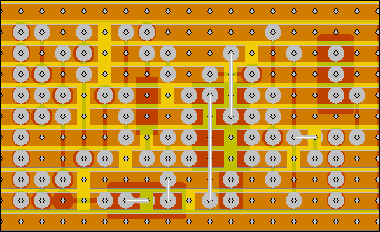
I've also updated the stripboard layouts a few posts back.
As well as changing the polarity of the resistor chain to +ve I also had to change the offset to -ve. After putting those two summed voltages through the inverting stage U101B you get the right voltages for the right positions on the rotary.
_________________
What makes a space ours, is what we put there, and what we do there. |
|
|
Back to top
|
|
|
|

 Forum index » DIY Hardware and Software