| Author |
Message |
Luka

Joined: Jun 29, 2007
Posts: 1003
Location: Melb.
|
|
|
Back to top
|
|
 |
andrewF

Joined: Dec 29, 2006
Posts: 1176
Location: australia
Audio files: 4
|
 Posted: Wed Oct 28, 2009 8:18 pm Post subject: Posted: Wed Oct 28, 2009 8:18 pm Post subject:
|
  |
|
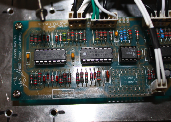
have you installed the link from pin3 of the lm324 to ground - next to the 47k?
otherwise post up some photos of the offending area and give us a look  |
|
|
Back to top
|
|
|
Luka
Joined: Jun 29, 2007
Posts: 1003
Location: Melb.
|
|
|
Back to top
|
|
|
andrewF
Joined: Dec 29, 2006
Posts: 1176
Location: australia
Audio files: 4
|
| Posted: Fri Oct 30, 2009 4:54 pm Post subject:
|
|
|
neat craftsmanship 
how have you wired the manual pwm pot, on the 6 pin plug it looks like there is no connection for 'R-' ? |
|
|
Back to top
|
|
|
Luka
Joined: Jun 29, 2007
Posts: 1003
Location: Melb.
|
| Posted: Sat Oct 31, 2009 8:56 am Post subject:
|
|
|
my pwm control is set up as voltage divider with -15 and +15 on each wiper
i have some rail buses attached to all necessary pots originating from the +ve -ve near the power inlet connector. i used the +R to send voltage to my grinder vactrol circuit
how does the dc offset work with a comperator circuit?
im still wondering if this is functioning properly
if i have no signal going into a comperator circuit apart from dc offset, shouldnt the comperator just shunt it to the negative or postive pole limits? when i do this and i try balance offset pot at 12 oclock it sometimes turns into a square wave and i can modify the pulse width with the pwm control. But if the offset is biased just a fraction to either pole it will just lock to the pole limit.
edit.
i suppose the comperator output voltage range should minic the input
_________________
problemchild
melbourne australia
http://cycleofproblems.blogspot.com/
http://www.last.fm/user/prblmchild |
|
|
Back to top
|
|
|
andrewF
Joined: Dec 29, 2006
Posts: 1176
Location: australia
Audio files: 4
|
| Posted: Sun Nov 01, 2009 6:06 pm Post subject:
|
|
|
| Quote: |
i have some rail buses attached to all necessary pots originating from the +ve -ve near the power inlet connector. i used the +R to send voltage to my grinder vactrol circuit
|
Thats what i do
| Quote: |
how does the dc offset work with a comperator circuit?
im still wondering if this is functioning properly
if i have no signal going into a comperator circuit apart from dc offset, shouldnt the comperator just shunt it to the negative or postive pole limits? when i do this and i try balance offset pot at 12 oclock it sometimes turns into a square wave and i can modify the pulse width with the pwm control. But if the offset is biased just a fraction to either pole it will just lock to the pole limit.
edit.
i suppose the comperator output voltage range should minic the input
|
The DC offset, I assume you mean the PWM pot here, sets the voltage level where the output of the comparator will change when the other input crosses this level. The PWM pot will be very sensitive around the mid-point as the comparator has no feedback circuit to stabilise it. A microvolt change on the DC-offset can be enough to flip the output.
The idea is to set the DC offset so the comparator output changes when the folded signal crosses say +2V, you could set the DC-offset so the comparator goes low at this point or goes high.
op-amps don't make good comparators as they are meant for linear operation, TL0XX are espcially bad at it as the output can get 'stuck' on the upper or lower rail. You may find at many settings the output is a sharp short pulse that is difficult to spot with a 'scope.
Looking at the schematic, the comparator output can only have two values : just under +15V and just above -15V (for a +/-15V supply). Theoretically you could get it to 0V, but don't even try |
|
|
Back to top
|
|
|
Luka
Joined: Jun 29, 2007
Posts: 1003
Location: Melb.
|
| Posted: Sun Nov 01, 2009 6:40 pm Post subject:
|
|
|
i meant from the manual offset knob which adds dc to the input signal feeding into the main signal
| Quote: | | Looking at the schematic, the comparator output can only have two values : just under +15V and just above -15V (for a +/-15V supply). Theoretically you could get it to 0V, but don't even try |
well that is how it works now
when i emailed ken about this he said that from my explanation that somethign was wrong with my circuit.
ken says-
| Quote: | | The offset should provide a smoothly variable change to the output signal - a "sweep" of sorts, so yes, you have something to worry about. |
i replied that my fold output works like this but the pulse output does not and he says yes there is a problem with my pcb build then.
im getting pretty confused with this, i re-searched comparator circuits and math all this morning and as far as i can tell my circuit is doing what it should. i might try feed a vco through it and see if it is functioning properly with a simple waveshape.
_________________
problemchild
melbourne australia
http://cycleofproblems.blogspot.com/
http://www.last.fm/user/prblmchild |
|
|
Back to top
|
|
|
andrewF
Joined: Dec 29, 2006
Posts: 1176
Location: australia
Audio files: 4
|
| Posted: Sun Nov 01, 2009 7:44 pm Post subject:
|
|
|
Glad to see you are having a busy Monday morning
sorry if this seems too obvious, I know you are an experienced builder.
With a VCO signal into the folder input.
can't remember if you hav a 'scope?
if so have a look at the 'folded' out signal in DC mode (on the 'scope setting). note the average voltage range of the signal, say between 0 and 4V.
Then put your probe on pin 1 of iC4 and adjust the PWM pot so the voltage on pin1 is approx halfway between the upper and lower voltages of the 'folded' output.
Now probe the pulse out, does it swing back n forth? If not = problem!
no scope? maybe you can do it with a multimeter, the precise valuse are not important, just the approx voltage range of the folded out signal is enough, and somewhere around the mid-point of that range on pin1.
The DCoffset on the input of the circuit affects folder behaviour (as Ken describes) rather than the offset of the signal when it reaches the folded output |
|
|
Back to top
|
|
|
Luka
Joined: Jun 29, 2007
Posts: 1003
Location: Melb.
|
| Posted: Sun Nov 01, 2009 8:28 pm Post subject:
|
|
|
hehe well before i was lurking on modular forums because i had some network problems that i couldnt fix, but i fixed that now, happy clients once again. Now i have to sift through complex abstracted census tables so here i am again
I'll check this stuff out tonight once i get home (yeh i have a scope)
thanks again andrew,
it is so awesome to have someone to help debug
_________________
problemchild
melbourne australia
http://cycleofproblems.blogspot.com/
http://www.last.fm/user/prblmchild |
|
|
Back to top
|
|
|
Luka
Joined: Jun 29, 2007
Posts: 1003
Location: Melb.
|
| Posted: Mon Nov 02, 2009 12:09 am Post subject:
|
|
|
ok i fed a tri wave from my evolver (boosted up to 10p-p with my mixer) into the comparator (pin 5 of ic4). it turns into a square wave. the thing now is that the manual pwm control just inverts the square instead of changing the width, and the manual offset knob changes the pulse width. this gets stranger by the second
this is with folds at 0 btw
_________________
problemchild
melbourne australia
http://cycleofproblems.blogspot.com/
http://www.last.fm/user/prblmchild |
|
|
Back to top
|
|
|
Luka
Joined: Jun 29, 2007
Posts: 1003
Location: Melb.
|
|
|
Back to top
|
|
|
andrewF
Joined: Dec 29, 2006
Posts: 1176
Location: australia
Audio files: 4
|
| Posted: Mon Nov 02, 2009 3:56 am Post subject:
|
|
|
good to know it works
enjoy it, its a very beautiful module for ambient slowly evolving sounds.
i mean the folder, not the grinder  the grinder is a beast the grinder is a beast |
|
|
Back to top
|
|
|
|

 Forum index » DIY Hardware and Software » Ken Stone designs - CGS