| Author |
Message |
acidblue
Joined: Jun 26, 2009
Posts: 226
Location: The Darkside
|
 Posted: Fri Nov 19, 2010 8:07 pm Post subject:
Led's on sequencer not sequencing Posted: Fri Nov 19, 2010 8:07 pm Post subject:
Led's on sequencer not sequencing |
  |
|
I made this sequencer from sea-moss and replaced the 22k resistors with pots and got it working fine--yippie!
http://milkcrate.com.au/_other/sea-moss/04_seq.gif
But now I want to add led's to flash in sequence.
But it dosen't work when I add a led and it's resistor to the corresponding pins on the 4051 IC in parallel, (pins 13,14,15,12 etc.).
In fact the whole sequencer stops sequencing.
Some of the led's are fully lit and some just barely.
I have the led and resistor connected in parallel from the pin to ground.
Like you would do on a 'Baby Ten' sequencer.
What am I doing wrong? |
|
|
Back to top
|
|
 |
rich decibels
Joined: Apr 01, 2010
Posts: 60
Location: Wellington, NZ
Audio files: 1
|
| Posted: Sat Nov 20, 2010 5:18 pm Post subject:
|
|
|
The 4051 is a multiplexer - it works like an 8-way switch. It takes whatever is on X and connects it to one of the pins X0-X7, depending on the state of the control inputs A, B, and C. In this case the 4040 is used to cycle through every combination of A, B, and C, so X gets connected to X0, X1, X2... in sequence.
Connecting LEDs to the output pins X0-X7 unfortunately won't do what you want it to do. If you redraw the schematic with the 4051 replaced with an 8-way switch, you'll see why: switching from one output to the next doesn't actually take any of the LEDs out of the circuit.
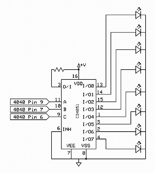
As far as I know, the only way to get indicators on a sequencer of this type is to use another 4051 whose A, B, and C, inputs are connected to the original 4040. Connect the X input to V+ via a limiting resistor (100-3k, depending on your LED), then connect each of the X0-X7 outputs to your 8 LEDs, which are then wired to ground.
There are probably more efficient ways of doing this. For instance, there are other kinds of multiplexers that have additional channels, so you could have the oscillator on one channel and the indicators on another. I've not done it myself though, so I can't tell you exactly where to look.
Good luck! |
|
|
Back to top
|
|
|
acidblue
Joined: Jun 26, 2009
Posts: 226
Location: The Darkside
|
| Posted: Sat Nov 20, 2010 7:23 pm Post subject:
|
|
|
| rich decibels wrote: |
As far as I know, the only way to get indicators on a sequencer of this type is to use another 4051 whose A, B, and C, inputs are connected to the original 4040. Connect the X input to V+ via a limiting resistor (100-3k, depending on your LED), then connect each of the X0-X7 outputs to your 8 LEDs, which are then wired to ground.
Good luck! |
That sort of works, The led's blink but they blink in unison not in sequence.
I might have it connected wrong, so let me be sure.
I have a second 4051 A, B, C pins connected to the original 4040 9, 7, 6 pins.
Plus pin 6 of the 4051 to ground. |
|
|
Back to top
|
|
|
rich decibels
Joined: Apr 01, 2010
Posts: 60
Location: Wellington, NZ
Audio files: 1
|
| Posted: Sat Nov 20, 2010 8:47 pm Post subject:
|
|
|
| Yeah it sounds as if it's wired up wrong. Rip everything out and start again! With multiplexers I always start with LEDs to indicate that everything is working before I move on to audio signals, which can be trickier to debug. |
|
|
Back to top
|
|
|
acidblue
Joined: Jun 26, 2009
Posts: 226
Location: The Darkside
|
| Posted: Sat Nov 20, 2010 8:56 pm Post subject:
|
|
|
Funny thing is the audio part works fine.
It sequences like it should, just the led's just don't sequence. |
|
|
Back to top
|
|
|
rich decibels
Joined: Apr 01, 2010
Posts: 60
Location: Wellington, NZ
Audio files: 1
|
| Posted: Sun Nov 21, 2010 12:46 am Post subject:
|
|
|
| you can verify your wiring by connecting A, B, and C to ground. only one LED should be lit. Now connect just A to V+, a different LED should light. and so on, one LED should light for each combination of GND and V+ on A, B, and C |
|
|
Back to top
|
|
|
acidblue
Joined: Jun 26, 2009
Posts: 226
Location: The Darkside
|
| Posted: Sun Nov 21, 2010 11:13 am Post subject:
|
|
|
| rich decibels wrote: | | you can verify your wiring by connecting A, B, and C to ground. only one LED should be lit. Now connect just A to V+, a different LED should light. and so on, one LED should light for each combination of GND and V+ on A, B, and C |
Do I do this on the original 4051 or the second? |
|
|
Back to top
|
|
|
rich decibels
Joined: Apr 01, 2010
Posts: 60
Location: Wellington, NZ
Audio files: 1
|
| Posted: Sun Nov 21, 2010 1:20 pm Post subject:
|
|
|
| On the second. The one with the LEDs... |
|
|
Back to top
|
|
|
stolenfat

Joined: Apr 17, 2008
Posts: 476
Location: Sunny Oakland California
Audio files: 1
|
| Posted: Sun Nov 21, 2010 2:14 pm Post subject:
|
|
|
this is what i had to do for my 4051 wacky sequencer...
pin->resister->led->output
just put the led in series. See if it that helps.
_________________
home made noise and electronic ill-logic |
|
|
Back to top
|
|
|
Scott Stites
Janitor


Joined: Dec 23, 2005
Posts: 4127
Location: Mount Hope, KS USA
Audio files: 96
|
|
|
Back to top
|
|
|
rich decibels
Joined: Apr 01, 2010
Posts: 60
Location: Wellington, NZ
Audio files: 1
|
| Posted: Sun Nov 21, 2010 4:33 pm Post subject:
|
|
|
| Good idea stolenfat - I assume that would mess with the sound somewhat? In a good way, obviously... |
|
|
Back to top
|
|
|
acidblue
Joined: Jun 26, 2009
Posts: 226
Location: The Darkside
|
| Posted: Sun Nov 21, 2010 4:59 pm Post subject:
|
|
|
AHA! That works.
Thanks guy's. |
|
|
Back to top
|
|
|
stolenfat
Joined: Apr 17, 2008
Posts: 476
Location: Sunny Oakland California
Audio files: 1
|
| Posted: Tue Nov 23, 2010 3:18 am Post subject:
|
|
|
| rich decibels wrote: | | Good idea stolenfat - I assume that would mess with the sound somewhat? In a good way, obviously... |
yessire.. the ol LED filter trick.
_________________
home made noise and electronic ill-logic |
|
|
Back to top
|
|
|
|

 Forum index » DIY Hardware and Software » Lunettas - circuits inspired by Stanley Lunetta