| Author |
Message |
Uncle Krunkus
Moderator

Joined: Jul 11, 2005
Posts: 4761
Location: Sydney, Australia
Audio files: 52
G2 patch files: 1
|
 Posted: Fri May 25, 2012 6:45 am Post subject:
The ReVibe Posted: Fri May 25, 2012 6:45 am Post subject:
The ReVibe
Subject description: New "stereo" sample of drum and bass |
  |
|
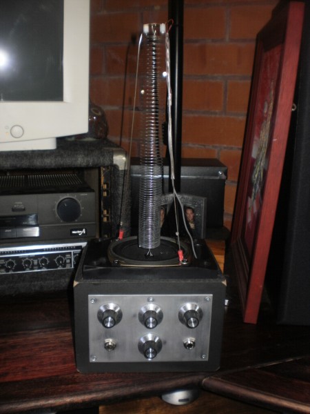
This is the other specimen on the slab at the moment.
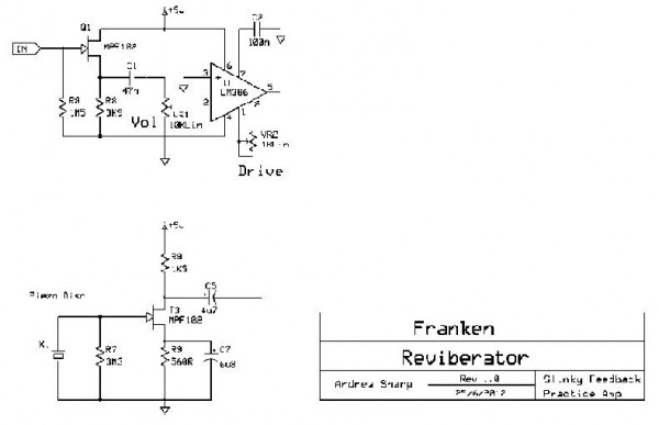
A slinky based reverb is just that, and I'm sure you're familiar with the following circuits. Of course the real work, (and payoffs) are in the way the transducers are constructed. I'll get some photos happening ASAP (  ) on this and other things. ) on this and other things.
What I'd like to know is,.....
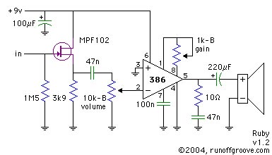
The first circuit (coil driver) is a basic Ruby Amplifier for a guitar practice amp. This works really well, and I've used it before. The second circuit (coil pickup) is a piezo pre-amp I've been using in the harp pre-amps I've been building lately.
I'd like part of the pickup signal to supply a feedback to the Ruby amp.
And I'd like the output to be a Wet/Dry blend.
The driver also doubles as a practice amp for virtually any instrument (even a modular?) and is very portable. Everything will run off a 9V battery.
The panel will hopefully have these points on it
Signal In
Signal Out
Drive (Ruby amp)
Level (Ruby amp)
Feedback
Wet / Dry
Does anyone have any suggestions about how to incorporate the Feedback, and Wet / Dry pots into these circuits?
| Description: |
|
| Filesize: |
15.4 KB |
| Viewed: |
22754 Time(s) |
|
| Description: |
|
| Filesize: |
11.73 KB |
| Viewed: |
22752 Time(s) |
|
_________________
What makes a space ours, is what we put there, and what we do there.
Last edited by Uncle Krunkus on Wed Jun 27, 2012 4:30 pm; edited 2 times in total |
|
|
Back to top
|
|
 |
Uncle Krunkus
Moderator
Joined: Jul 11, 2005
Posts: 4761
Location: Sydney, Australia
Audio files: 52
G2 patch files: 1
|
| Posted: Sun Jun 03, 2012 4:54 am Post subject:
|
|
|
Okay,
So the driver circuit is virtually as is on the schem above.
The piezo pick-up circuit is as above minus the 220K output resistor to ground, Just the 4u7 to a 100Klin variable resistor and into another 4u7 back to a point on the amp. But which point?
I'm thinking to the top of the volume pot. Not sure why, just feels right.
I'm also going to incorporate a phase switch, which will be just a cross-over on a DPDT switch to the speaker. This is to enhance the cancellation of the driver, direct through the tower, thus emphasising the spring vibrations coming into the piezo. The physical structure would change with every incarnation, so being able to divide out half the resonant frequencies, would always be handy.
I've got to get some photos up for this, it would be so much easier for you to see what I'm dealing with.
_________________
What makes a space ours, is what we put there, and what we do there. |
|
|
Back to top
|
|
|
JingleJoe

Joined: Nov 10, 2011
Posts: 878
Location: Lancashire, England
Audio files: 14
|
| Posted: Sun Jun 03, 2012 5:37 am Post subject:
|
|
|
| Uncle Krunkus wrote: |
I'm thinking to the top of the volume pot. Not sure why, just feels right.
|
Yes, you can leave off all the components to the left of that 47n cap connected to the pot really, they seem to be there to increase the input impedance.
(apart from the 100uF accross the power supply, thats important for smoothing the power supply, even from a battery)
Wet/dry feedback seems like it would just be filtered high pass and low pass then mixed back in. Not certain about that though but it seems pretty likely that's what is done.
_________________
As a mad scientist I am ruled by the dictum of science: "I could be wrong about this but lets find out"
Green Dungeon Alchemist Laboratories |
|
|
Back to top
|
|
|
Uncle Krunkus
Moderator
Joined: Jul 11, 2005
Posts: 4761
Location: Sydney, Australia
Audio files: 52
G2 patch files: 1
|
| Posted: Sun Jun 03, 2012 6:42 am Post subject:
|
|
|
Finished the first step, put it back together, and it's actually sounding pretty good, but mostly cos of it's own, low frequency self oscillation. Sounds creepy indeed.
Now I need a High Pass filter for the feedback path, so I can tame this beautiful rumble.
_________________
What makes a space ours, is what we put there, and what we do there. |
|
|
Back to top
|
|
|
Uncle Krunkus
Moderator
Joined: Jul 11, 2005
Posts: 4761
Location: Sydney, Australia
Audio files: 52
G2 patch files: 1
|
|
|
Back to top
|
|
|
Uncle Krunkus
Moderator
Joined: Jul 11, 2005
Posts: 4761
Location: Sydney, Australia
Audio files: 52
G2 patch files: 1
|
|
|
Back to top
|
|
|
JingleJoe
Joined: Nov 10, 2011
Posts: 878
Location: Lancashire, England
Audio files: 14
|
| Posted: Mon Jun 04, 2012 5:29 am Post subject:
|
|
|
That looks friggen incredible, I would love to make one as reverb/echo is something I am in need of. However the interesting but unintentional ambient sounds it makes would probably mean loud sounds would interfere with it, lets call that an undocumented feature  . .
I tried to make a slinky reverb once in a very similar way but got no good results, at the time I don't think I knew enough about electronics to manipulate the signal properly. What did you do to determine slinky taughtness? did you just stretch out a length or was there significant experimentation? Can you change the slinky slack to get different reverberations?
_________________
As a mad scientist I am ruled by the dictum of science: "I could be wrong about this but lets find out"
Green Dungeon Alchemist Laboratories |
|
|
Back to top
|
|
|
Uncle Krunkus
Moderator
Joined: Jul 11, 2005
Posts: 4761
Location: Sydney, Australia
Audio files: 52
G2 patch files: 1
|
| Posted: Mon Jun 04, 2012 6:05 am Post subject:
|
|
|
I've stretched it to the point where the layers of coil don't "chatter" against each other. This is a personal preference I s'pose, but it's not a very musical or controllable sound. And with all the various ways of driving the coil, and adding what is already too much (better too much than not enough ) feedback, I'm sure it is still capable of some pretty noisy stuff. I can shorten any particular slinky, but can't put length back, so I'll leave it here till further tests deem otherwise. Apart from that, you shouldn't stretch it too far, as that will raise the fundamental resonant frequency of the spring, possibly into the realm where you want it to work.
The little discs you can see between two of the coils, are rare earth magnets, broken out of those magnetic building bars. They are very re-locatable, and seem to afford a bit of control when it comes to dampening the standing waves, as they add their own dischordant magnetic fields, and are quite heavy for their size, and so can be placed to fix the "nodes" in the spring. If you know about wave theory, you'll get what I mean.
The main trick is to maximise the signal transfer into the spring, and minimise the dry spill into the tower structure. This is a tricky thing to do. But that's why I made it this way. Almost everything can be re-built, if and when I decide to change it.
The slinky is a standard "Toyworld" slinky. I bought 5 wrapped in plastic for $1 each. They're made in Taiwan. Should be easy to find something similar. Solder a loop across both ends at the right cut off point. Solder a copper wire hook onto the back of a piezo (brass side) and drill two 2-2.5mm holes at the edges. The supports are 1.5-2mm piano wire, with a crimp type eyelet crimped onto the bottom to put under the driver screws. At the other end, bend an angle and solder a 2-2.5 mm nut at right angles.
Use spacers if need be to hold the piezo at the right distance from the spring.
Super glue a hook (copper wire) to the middle of the driver, and you should be right to go.
Next job is to put a DPDT change-over on the speaker connections so the drive phase can be swapped. I'm thinking that could be a good place to put a passive second order HPF on the driver while I'm at it. I know I don't want the lower frequencies setting up standing waves, so this is a basic part of the setup which needs to be sorted out now, before anymore testing goes on.
I thought of incorporating Ray Wilson's WSG filter on the feedback path, but I'm not sure if this is overkill on the feature creep side, and would drain the 9V battery much faster (uses a 741 op-amp). Do you think it's worth trying? Not sure.
Well, it's heaps better than two other spring based reverbs I have played with in the past, so I s'pose I'm making some headway. I actually love the sound of it's rumblings at this stage. It's almost like an electronic digeridoo. Recording wise, it would need a vibration free environment, but the potential for driving an effect signal is already good.
_________________
What makes a space ours, is what we put there, and what we do there. |
|
|
Back to top
|
|
|
JingleJoe
Joined: Nov 10, 2011
Posts: 878
Location: Lancashire, England
Audio files: 14
|
| Posted: Mon Jun 04, 2012 1:05 pm Post subject:
|
|
|
I love the rumbling sound too  Just doesn't make a good contraption for live performance at a loud gig though Nevertheless I may experiment with something like this again seeing your good results with a piezo sounder (bought a few a while back to make a beeping box for a friend) Just doesn't make a good contraption for live performance at a loud gig though Nevertheless I may experiment with something like this again seeing your good results with a piezo sounder (bought a few a while back to make a beeping box for a friend)
As for the WSG filter, I have built it with other lower power op amps and it still works well
_________________
As a mad scientist I am ruled by the dictum of science: "I could be wrong about this but lets find out"
Green Dungeon Alchemist Laboratories |
|
|
Back to top
|
|
|
Uncle Krunkus
Moderator
Joined: Jul 11, 2005
Posts: 4761
Location: Sydney, Australia
Audio files: 52
G2 patch files: 1
|
| Posted: Tue Jun 05, 2012 5:16 pm Post subject:
|
|
|
What I'm thinking now is that a device like this actually has two types of feedback happening at the same time.
There's the controlled feedback of the piezo pickup being fed back into the driver. The fact that this is controlled means I could add any type of filter I like to enhance or minimise this effect. I'll get back to this issue later.
But there is also the mechanical feedback which means that some of the driver signal shakes the "tower" and induces low frequency rumblings back into the piezo. This second type of feedback has only a bad effect on the output, unless you purposely want to setup standing waves to create a spring digeridoo. But this would still be possible using controlled electronic feedback via the first method.
So, today I'm going to attack the mechanical feedback by simply putting a bi-polar (crossover) cap across the driver speaker. I'm also going to try reversing the phase of the drive signal at the speaker connections.
I'll post some audio samples (soon) which will hopefully show a reduction in the low frequency oscillations.
_________________
What makes a space ours, is what we put there, and what we do there. |
|
|
Back to top
|
|
|
Uncle Krunkus
Moderator
Joined: Jul 11, 2005
Posts: 4761
Location: Sydney, Australia
Audio files: 52
G2 patch files: 1
|
|
|
Back to top
|
|
|
JingleJoe
Joined: Nov 10, 2011
Posts: 878
Location: Lancashire, England
Audio files: 14
|
| Posted: Wed Jun 06, 2012 2:16 am Post subject:
|
|
|
Sounds cool!  I got around the chattering by doing that too, just stretching the spring a bit more so the rings don't touch. Carry on the good work, I look forwards to seeing more of this I got around the chattering by doing that too, just stretching the spring a bit more so the rings don't touch. Carry on the good work, I look forwards to seeing more of this
_________________
As a mad scientist I am ruled by the dictum of science: "I could be wrong about this but lets find out"
Green Dungeon Alchemist Laboratories |
|
|
Back to top
|
|
|
Uncle Krunkus
Moderator
Joined: Jul 11, 2005
Posts: 4761
Location: Sydney, Australia
Audio files: 52
G2 patch files: 1
|
| Posted: Wed Jun 06, 2012 8:20 pm Post subject:
Some more photos |
|
|
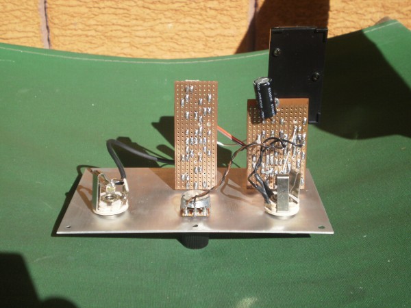
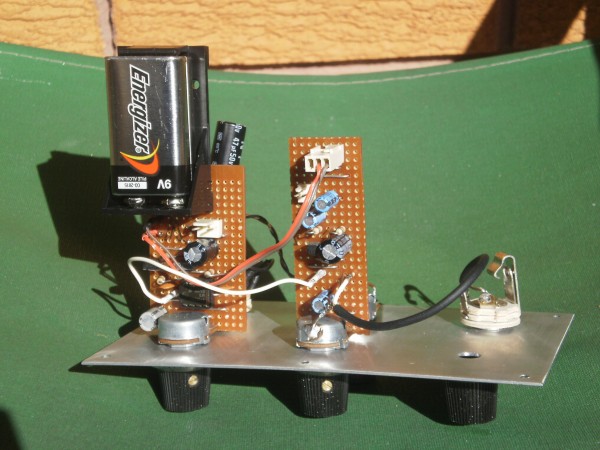
I took a few pics of the guts of it at this stage.
| Description: |
|
| Filesize: |
815.78 KB |
| Viewed: |
391 Time(s) |
| This image has been reduced to fit the page. Click on it to enlarge. |
|
| Description: |
|
| Filesize: |
770.11 KB |
| Viewed: |
413 Time(s) |
| This image has been reduced to fit the page. Click on it to enlarge. |
|
_________________
What makes a space ours, is what we put there, and what we do there. |
|
|
Back to top
|
|
|
elmegil

Joined: Mar 20, 2012
Posts: 2179
Location: Chicago
Audio files: 16
|
| Posted: Wed Jun 06, 2012 9:24 pm Post subject:
|
|
|
| That's an interesting 9V mount, where is it from? |
|
|
Back to top
|
|
|
JingleJoe
Joined: Nov 10, 2011
Posts: 878
Location: Lancashire, England
Audio files: 14
|
| Posted: Thu Jun 07, 2012 5:07 am Post subject:
|
|
|
I like the way you have mounted the boards by the (edit) potentiometers I might have to do that in the future with some of mine!
I've seen those 9V, PP3 battery holders everywhere, have a look on rapid or some other electronic components website.
_________________
As a mad scientist I am ruled by the dictum of science: "I could be wrong about this but lets find out"
Green Dungeon Alchemist Laboratories
Last edited by JingleJoe on Thu Jun 07, 2012 9:14 am; edited 1 time in total |
|
|
Back to top
|
|
|
Uncle Krunkus
Moderator
Joined: Jul 11, 2005
Posts: 4761
Location: Sydney, Australia
Audio files: 52
G2 patch files: 1
|
| Posted: Thu Jun 07, 2012 5:58 am Post subject:
|
|
|
No, not mounted by the capacitors, mounted by the pots.
Or are you takin the piss Joe? 
Today I suddenly realised that the overabundance of feedback and self oscillation was due to the fact that my feedback pot was set up simply as a variable resistor of 25KLin. So even when it was turned down low, 25K is too much feedback. It was just simply pumping too much signal back. That meant that the main Volume had to be too low to actually drive the spring.
So,.....
I replaced it with a 500KLin pot, and,.... wow,......!!!
Now, it's super easy to dial up a weird spring reverb on whatever input I like.
I still have a bit of spring chatter, which I may or may not try to eliminate, but, for now, I'm pretty happy with these kinda sounds.
Sorry that this sample is so long and self indulgent, but I think it resolves itself really well. Terrible guitar vamping followed by a journey into resonance.
Bon Appetite!
| Description: |
|

Download (listen) |
| Filename: |
Slinky Amp 7-6-12.mp3 |
| Filesize: |
5.49 MB |
| Downloaded: |
1193 Time(s) |
_________________
What makes a space ours, is what we put there, and what we do there. |
|
|
Back to top
|
|
|
elmegil
Joined: Mar 20, 2012
Posts: 2179
Location: Chicago
Audio files: 16
|
| Posted: Thu Jun 07, 2012 6:56 am Post subject:
|
|
|
| Thanks Joe, "PP3" was the magic I needed |
|
|
Back to top
|
|
|
prgdeltablues
Joined: Sep 25, 2006
Posts: 222
Location: UK
Audio files: 12
|
| Posted: Thu Jun 07, 2012 7:24 am Post subject:
|
|
|
Love it!
Can you say a bit more about how you attach the coil to the driver - and what size is the driver (I take it it's just an ordinary speaker cone) - you said a copper hook super-glued on, but to where precisely, and do you cut the paper cone out?
Would using rubber compression washers on the fixings between the support wires to the base help cut down mechanical feedback?
Peter |
|
|
Back to top
|
|
|
JingleJoe
Joined: Nov 10, 2011
Posts: 878
Location: Lancashire, England
Audio files: 14
|
| Posted: Thu Jun 07, 2012 9:13 am Post subject:
|
|
|
| Uncle Krunkus wrote: | No, not mounted by the capacitors, mounted by the pots.
Or are you takin the piss Joe? |
arg! sorry, temporary lapse of coherant thought, I meant to write potentiometers I will edit it.
_________________
As a mad scientist I am ruled by the dictum of science: "I could be wrong about this but lets find out"
Green Dungeon Alchemist Laboratories |
|
|
Back to top
|
|
|
JingleJoe
Joined: Nov 10, 2011
Posts: 878
Location: Lancashire, England
Audio files: 14
|
| Posted: Thu Jun 07, 2012 9:16 am Post subject:
|
|
|
P.S. that sounds amazing now  I MUST MAKE ONE. I MUST MAKE ONE.
Can we get a circuit diagram or basic block diagram showing feedback?
_________________
As a mad scientist I am ruled by the dictum of science: "I could be wrong about this but lets find out"
Green Dungeon Alchemist Laboratories |
|
|
Back to top
|
|
|
Uncle Krunkus
Moderator
Joined: Jul 11, 2005
Posts: 4761
Location: Sydney, Australia
Audio files: 52
G2 patch files: 1
|
| Posted: Mon Jun 25, 2012 6:37 am Post subject:
|
|
|
I was playing around with this again tonight, and it's actually really cool. Maybe I could take a couple more rings off the coil, but the first thing is I need to increase the feedback pot even more. With it set on "0" I can't get the volume above about 35% without starting a constant standing wave. At about 30% it will fade right off to nothing.
Even just tweaking these three controls, (Vol, Drive & Feedback) and dampening the "tower" with your hand, or tapping the spring, or just muting the piezo, produces all these really nice rythym sounds. Some great stuff for sampling and turning into drums, drones, bass, and glitchy stuff.
Yes,.. I know I haven't done that scheme yet have I Joe?
Well, I'm gonna get right on it. This is really worth building. I'd love to see the different driver/spring/piezo constructions people might come up with.
_________________
What makes a space ours, is what we put there, and what we do there. |
|
|
Back to top
|
|
|
StephenGiles
Joined: Apr 17, 2006
Posts: 507
Location: England
|
| Posted: Mon Jun 25, 2012 7:31 am Post subject:
|
|
|
| Uncle Krunkus wrote: | I used a 47uF bi-polar directly across the speaker connections, and there is an immediate improvement in effect signal over unwanted feedback, and a reduction in rumbling. It's heaps easier to control. The fact that I can set it to effect the input without holding a standing wave at all is a great leap forward in itself.
The next issue is that the "chattering" of the spring coils tapping against each other is quite obvious in this sample. This is where the shortening of the spring will now be of good effect. I'm quite certain just a couple of layers snipped off will both reduce the chattering and slightly raise the fundamental resonance of the spring. Also, I currently have the spring held in place by it's own tension in the "hooks". I'll try fixing these points solid first and see what effect I get. |
Hey, the first section is almost the chords to "Walk Don't Run" !! |
|
|
Back to top
|
|
|
Uncle Krunkus
Moderator
Joined: Jul 11, 2005
Posts: 4761
Location: Sydney, Australia
Audio files: 52
G2 patch files: 1
|
|
|
Back to top
|
|
|
Uncle Krunkus
Moderator
Joined: Jul 11, 2005
Posts: 4761
Location: Sydney, Australia
Audio files: 52
G2 patch files: 1
|
| Posted: Mon Jun 25, 2012 7:37 am Post subject:
|
|
|
Nuh, that looks shithouse!
I'm gonna have to install photoshop before I can get any decent images happening on this computer. 
_________________
What makes a space ours, is what we put there, and what we do there. |
|
|
Back to top
|
|
|
Uncle Krunkus
Moderator
Joined: Jul 11, 2005
Posts: 4761
Location: Sydney, Australia
Audio files: 52
G2 patch files: 1
|
| Posted: Tue Jun 26, 2012 4:58 am Post subject:
|
|
|
Well,
Today my main computer decided that it didn't have USB ports no more!! 
So I couldn't get anything off there. (They're on the same network, you'd think I could sort that out hey? )
Anyway,...
I finally found an old archive CD, and it had an old copy of photoshop on it.
So here is my new, improved schematic posting cred. Tiny file, big resolution.
I just updated the pic,
all the designators are right now.
I hope someone has some ideas how it might be made even better.
| Description: |
|
| Filesize: |
19.12 KB |
| Viewed: |
591 Time(s) |
| This image has been reduced to fit the page. Click on it to enlarge. |
|
_________________
What makes a space ours, is what we put there, and what we do there. |
|
|
Back to top
|
|
|
|

 Forum index » DIY Hardware and Software