| Author |
Message |
Thomas_Henry
Joined: Jul 24, 2009
Posts: 170
Location: N. Mankato, MN
Audio files: 3
|
 Posted: Thu Mar 06, 2014 5:44 pm Post subject:
An Easy AD Envelope Generator Posted: Thu Mar 06, 2014 5:44 pm Post subject:
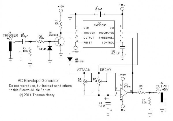
An Easy AD Envelope Generator
Subject description: Very snappy, yet simple to build! |
  |
|
Hi Gang,
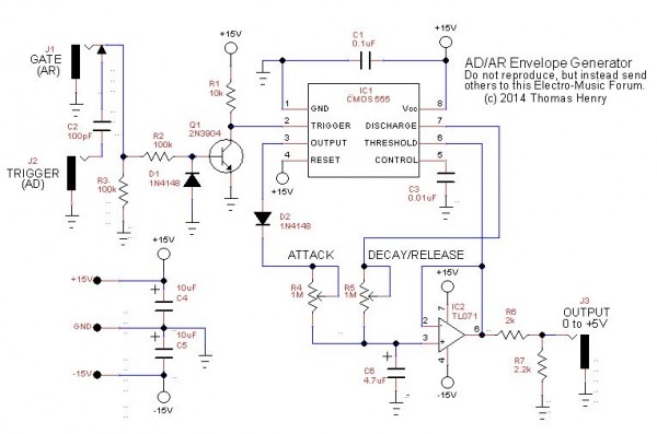
I saw a circuit for an AD envelope generator elsewhere on this forum and instantly thought it was way too complicated:
So, just as a diversion, I decided to come up with one that does the same thing, but with far fewer parts.
Here's the scoop. Most people think of the 555 as a timer, either astable or monostable, which tends to lock one into a rigid way of thinking. I prefer to think of the chip as a collection of parts. In particular, the circuit mentioned above requires an RS flip-flop, a comparator and some steering logic (diodes). In fact the 555 contains these. (Well, I did have provide one steering diode, the other imitated by the internal open collector transistor).
In one fell swoop (the only kind of swoop worth having), the circuit shrinks by leaps and bounds.
My good buddy Scott Stites gave it a shakedown with the test instruments and measured:
Minimum attack: 692 us
Minimum decay: 248 us
Maximum attack: 4.6 s
Maximum decay: 25.8 s
Max voltage: 5.04V
These are pretty specs, if I may be so immodest. It would also make a fine drum envelope generator, methinks.
Thomas Henry
| Description: |
|
| Filesize: |
41.32 KB |
| Viewed: |
4239 Time(s) |
| This image has been reduced to fit the page. Click on it to enlarge. |
|
|
|
|
Back to top
|
|
 |
mrmrshoes
Joined: Feb 19, 2011
Posts: 73
Location: Newcastle Upon Tyne
Audio files: 4
|
| Posted: Thu Mar 06, 2014 6:59 pm Post subject:
|
|
|
Man great work as always. thanks for sharing.
you sure have gotten your moneys worth from the 555 like 
I'll breadboard this up as soon as. |
|
|
Back to top
|
|
|
mcop

Joined: Apr 27, 2012
Posts: 46
Location: Brighton UK
|
| Posted: Fri Mar 07, 2014 1:45 am Post subject:
|
|
|
| Oooh! Thanks, going to try this one as well. Another elegantly simple design. |
|
|
Back to top
|
|
|
mcop
Joined: Apr 27, 2012
Posts: 46
Location: Brighton UK
|
|
|
Back to top
|
|
|
Thomas_Henry
Joined: Jul 24, 2009
Posts: 170
Location: N. Mankato, MN
Audio files: 3
|
| Posted: Fri Mar 07, 2014 9:45 am Post subject:
|
|
|
Thanks for the comments.
The comparator add-on is unneeded; the original circuit will work directly with a gate input. The cap and transistor already differentiate whatever is applied, gate or trigger.
Thomas Henry |
|
|
Back to top
|
|
|
mcop
Joined: Apr 27, 2012
Posts: 46
Location: Brighton UK
|
| Posted: Fri Mar 07, 2014 10:07 am Post subject:
|
|
|
| Thomas_Henry wrote: | Thanks for the comments.
The comparator add-on is unneeded; the original circuit will work directly with a gate input. The cap and transistor already differentiate whatever is applied, gate or trigger. |
Quite right, I wasn't trying to find fault with your design, I'm not in your league knowledge wise.
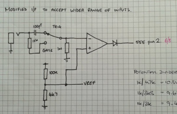
The reason I added the comparator was for a couple of reasons. The main reason was so I could trigger it with samples of trigger pulses from my Akai MPC as well as from my modular. Hence the low threshold voltage on the comparator.
The other was so I could feed it a gate signal and either use it as an AR envelope where the envelope stays high (once the attack reaches maximum) for as long as the gate lasts. When selecting the input through the original capacitor it stays as a AD envelope regardless of gate length.
Could I have achieved this simply by putting a bypass switch on the 100pF capacitor? As I trigger from my MPC manually the velocity and hence the level of the trigger pulses vary and I wanted to account for this. |
|
|
Back to top
|
|
|
StephenGiles
Joined: Apr 17, 2006
Posts: 507
Location: England
|
| Posted: Fri Mar 07, 2014 12:10 pm Post subject:
|
|
|
| Hi Tom, great circuit as usual! From a guitarist's viewpoint, could the peak voltage level of the attack phase be controlled by a voltage extracted from a "pluck follower"? (Craig Anderton's AMS 100?) The point being that if the AD output drives a VCF, the smooth decay phase should be completely ripple free. |
|
|
Back to top
|
|
|
Thomas_Henry
Joined: Jul 24, 2009
Posts: 170
Location: N. Mankato, MN
Audio files: 3
|
| Posted: Fri Mar 07, 2014 12:16 pm Post subject:
|
|
|
Hey Mcop,
Try this. Just wire a SPST switch across the input cap. When closed, the unit becomes an AR envelope generator, when open it is an AD type. I find I can fire it either way with a gate or trigger whose amplitude is at least 1.8V.
I'll add the switch in the next draft. Thanks for suggesting it.
Thomas Henry |
|
|
Back to top
|
|
|
Thomas_Henry
Joined: Jul 24, 2009
Posts: 170
Location: N. Mankato, MN
Audio files: 3
|
|
|
Back to top
|
|
|
mcop
Joined: Apr 27, 2012
Posts: 46
Location: Brighton UK
|
| Posted: Sat Mar 08, 2014 9:50 am Post subject:
|
|
|
Thanks, will try this when I get a chance to get back to my breadboard.
| Thomas_Henry wrote: | | Try this. Just wire a SPST switch across the input cap. |
|
|
|
Back to top
|
|
|
seanpark
Joined: Mar 15, 2013
Posts: 4
Location: nashville
|
| Posted: Mon Mar 10, 2014 8:48 pm Post subject:
|
|
|
This is quite an efficient circuit!
Patched up a bass drum sound, breadboarded this thing and bam.
First time I've used an AD. Thanks, Thomas! Cool circuit.
Been reading the Drum Cookbook a few times through, maybe its time to start building some things. |
|
|
Back to top
|
|
|
StephenGiles
Joined: Apr 17, 2006
Posts: 507
Location: England
|
| Posted: Tue Mar 11, 2014 12:51 am Post subject:
|
|
|
| StephenGiles wrote: | | Hi Tom, great circuit as usual! From a guitarist's viewpoint, could the peak voltage level of the attack phase be controlled by a voltage extracted from a "pluck follower"? (Craig Anderton's AMS 100?) The point being that if the AD output drives a VCF, the smooth decay phase should be completely ripple free. |
Any thoughts anyone? |
|
|
Back to top
|
|
|
wackelpeter
Joined: May 05, 2013
Posts: 461
Location: germany
Audio files: 10
|
| Posted: Tue Mar 11, 2014 10:09 am Post subject:
|
|
|
would this work with an ne555 too or must that be an cmos 555 ic? just asking as i have some spare NE555 already here but no CMOS timers at hand right now...
Please forgive me taht stupid question but my basic electronical lessons are now roughly 20 years ago so only a few things of that small knowledge left in those few of my braincells that continue working until today
Looking at the datasheet i would say it could work that way too or i am wrong? |
|
|
Back to top
|
|
|
bubzy

Joined: Oct 27, 2010
Posts: 594
Location: United Kingdom
Audio files: 64
|
|
|
Back to top
|
|
|
mcop
Joined: Apr 27, 2012
Posts: 46
Location: Brighton UK
|
|
|
Back to top
|
|
|
Thomas_Henry
Joined: Jul 24, 2009
Posts: 170
Location: N. Mankato, MN
Audio files: 3
|
| Posted: Tue Mar 11, 2014 11:42 pm Post subject:
|
|
|
Hello all,
I'm delighted to see a few folks are having fun with this.
This might be a good time to remind E-M people, that I do have special arrangements with Scott Stites, Tim Servo and Fonik for applications and dispersal of my designs. In fairness to them, be sure to secure permission from both me and them before posting any sort of derivative work that could cut into the hours they have spent or are spending spreading this stuff around. All it takes is a request, and I've rarely turned anyone down if I know what is coming.
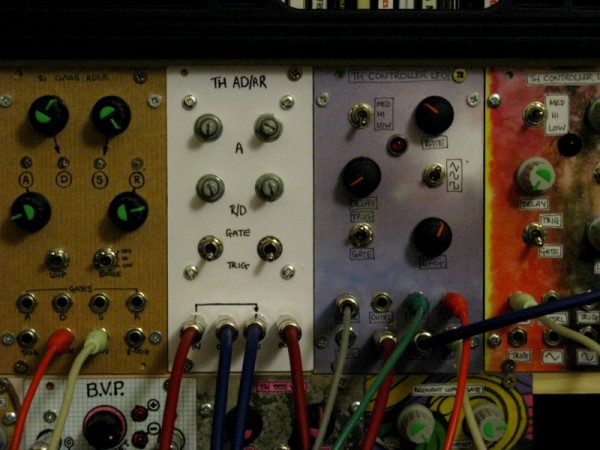
Otherwise, feel free to make your own versions for private use and let us know your results. For example, Mcop's rendition looks just great!
Thanks,
Thomas Henry |
|
|
Back to top
|
|
|
bubzy
Joined: Oct 27, 2010
Posts: 594
Location: United Kingdom
Audio files: 64
|
| Posted: Wed Mar 12, 2014 12:39 am Post subject:
|
|
|
sorry Thomas, would you like me to remove the pcb artwork?
_________________
_Richard_  |
|
|
Back to top
|
|
|
StephenGiles
Joined: Apr 17, 2006
Posts: 507
Location: England
|
| Posted: Wed Mar 12, 2014 1:13 am Post subject:
|
|
|
| StephenGiles wrote: | | StephenGiles wrote: | | Hi Tom, great circuit as usual! From a guitarist's viewpoint, could the peak voltage level of the attack phase be controlled by a voltage extracted from a "pluck follower"? (Craig Anderton's AMS 100?) The point being that if the AD output drives a VCF, the smooth decay phase should be completely ripple free. |
Any thoughts anyone? |
I'll take that as a no then  |
|
|
Back to top
|
|
|
Thomas_Henry
Joined: Jul 24, 2009
Posts: 170
Location: N. Mankato, MN
Audio files: 3
|
| Posted: Wed Mar 12, 2014 12:03 pm Post subject:
|
|
|
Hi Stephen,
Sorry, I kept overlooking your question somehow.
If I understand it properly, I do believe the answer is no, at least for this circuit. The envelope peak is set by those three series resistors inside the 555. This is the divider that sets the comparator thresholds. Look at a block diagram for the 555 and you'll see how 10 volts is the magic number for the peak.
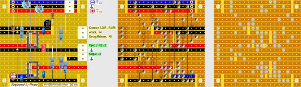
I will be incorporating this circuit within a complete synth voice, and providing artwork myself for a PCB, possibly for an article. But, Bubzy, you can leave what you have done up for others to play with.
And Wackelpeter, this is such a small circuit, that the easiest way to answer your question is just to breadboard it and see if a bipolar 555 will work. There will probably be some difference in how the internal transistor on pin 7 behaves which might affect the decay, but logically the circuit should work the same.
Thomas Henry |
|
|
Back to top
|
|
|
wackelpeter
Joined: May 05, 2013
Posts: 461
Location: germany
Audio files: 10
|
| Posted: Wed Mar 12, 2014 1:13 pm Post subject:
|
|
|
Hi Thomas,
thanks for your reply... still had built this circuit on stripboard, but only got the same signal on output which i fed to the input... that was the reason why i wasn't sure... and now checking my stripboard again with an magnifiying glass i found a strip not drilled correctly which shorted the input after the condensator with the output... well that's stupidity at work so please don't laugh at me.. it's the usual thing that i oversee the simple mistakes i made... don't wanted to show that i'm an idiot what i now have to admit
With that strip fully parted no wonder it works...
But now i have to re-work my power supply as my self-built one after Ken Stone's design doesn't work properly... voltage drops down the more modules i'm connecting to it... it's as i assume not the current as i have 60mA fuses on each rail it's the transformer 2x24AC that feeds a bit too much to the15V DC Regulators i think.... will go for an traco power supply unit so far... Guess that also is the issue for some of my other problems... LFO clicking in my Steiner Parker filter as each cycle of the lfo the voltage goes down on the positive rail... i'll see what of These issues left when i run everything on a stable psu...
Thank you again Thomas and sorry for entering this thread with my other issues...
Keep your nice work going. |
|
|
Back to top
|
|
|
StephenGiles
Joined: Apr 17, 2006
Posts: 507
Location: England
|
| Posted: Wed Mar 12, 2014 1:30 pm Post subject:
|
|
|
| Thomas_Henry wrote: | Hi Stephen,
Sorry, I kept overlooking your question somehow.
If I understand it properly, I do believe the answer is no, at least for this circuit. The envelope peak is set by those three series resistors inside the 555. This is the divider that sets the comparator thresholds. Look at a block diagram for the 555 and you'll see how 10 volts is the magic number for the peak.
I will be incorporating this circuit within a complete synth voice, and providing artwork myself for a PCB, possibly for an article. But, Bubzy, you can leave what you have done up for others to play with.
And Wackelpeter, this is such a small circuit, that the easiest way to answer your question is just to breadboard it and see if a bipolar 555 will work. There will probably be some difference in how the internal transistor on pin 7 behaves which might affect the decay, but logically the circuit should work the same.
Thomas Henry |
Thanks Thomas, I'll check out the 555 innards. |
|
|
Back to top
|
|
|
Nardu

Joined: Feb 28, 2011
Posts: 62
Location: Braila, Romania
|
|
|
Back to top
|
|
|
elmegil

Joined: Mar 20, 2012
Posts: 2179
Location: Chicago
Audio files: 16
|
| Posted: Wed Mar 12, 2014 7:22 pm Post subject:
|
|
|
| wackelpeter wrote: | Hi Thomas,
thanks for your reply... still had built this circuit on stripboard, but only got the same signal on output which i fed to the input... that was the reason why i wasn't sure... and now checking my stripboard again with an magnifiying glass i found a strip not drilled correctly which shorted the input after the condensator with the output... well that's stupidity at work so please don't laugh at me.. it's the usual thing that i oversee the simple mistakes i made... don't wanted to show that i'm an idiot what i now have to admit |
We all have done it; the only laughter will be the one of recognition and being glad you've found it  |
|
|
Back to top
|
|
|
wackelpeter
Joined: May 05, 2013
Posts: 461
Location: germany
Audio files: 10
|
| Posted: Thu Mar 13, 2014 9:28 am Post subject:
|
|
|
| elmegil wrote: |
We all have done it; the only laughter will be the one of recognition and being glad you've found it |
well glad to hear that i'm not the only one tapping in that trap.. it's maybe a bit like searching for your glasses whilst having them already on your nose... the easiest explanations are thrown in the background when going into detail and therefore are overseen...
meanwhile as it's working perfectly and i today got hold of some Cmos 555ers and furthermore there's some space on my stripboard left i'll buy another one and will look if they behave that different at all...
p.s. whilst i always do my builts on stripboard i would maybe in the future try to change to printed pcb's... therefore i would like to ask you guys who make the pcb's or let them get printed, how you handle it normally... do you always or mostly take some more pcb's than you have pre-orders for and would sell and send them to someone who ask and pay for them afterwards?
this question is especially adressed to those living in germany or europe as actual postage costs from the united states are really high...
would be a nice thing to switch from stripboard to "real" pcb and i don't have that drilling/cutting issue anymore... besides that the need to "only" placing and soldering components on pcb will be much faster than doing anything on stripboard... |
|
|
Back to top
|
|
|
mcop
Joined: Apr 27, 2012
Posts: 46
Location: Brighton UK
|
| Posted: Thu Mar 13, 2014 10:06 am Post subject:
|
|
|
| If there are runs of boards happening people normally start threads to see what interest there is both here and at muffwigler.com. Fonik in particular has done some excellent boards for some of Thomas' other designs. |
|
|
Back to top
|
|
|
|

 Forum index » DIY Hardware and Software » Thomas Henry designs