| Author |
Message |
Samuxx
Joined: Aug 24, 2016
Posts: 6
Location: Munich
|
 Posted: Wed Aug 24, 2016 10:48 am Post subject:
Sample & Hold Malfunction Posted: Wed Aug 24, 2016 10:48 am Post subject:
Sample & Hold Malfunction
Subject description: No output at s&h |
  |
|
Hi!
I built myself a quite nice Modular Synth - Yusynth layouts. But this very last module is finishing me off! This is already my second pcb try.  - Noise works well... - Noise works well...
The sample rate works, as well as the led. But when i give input to the s&h (for example white noise) - nothing. At the middle position of the slew rate pot I get some very quiet sound (about 8000hz) beeping in the rythm of the sample rate.
BC547C as Q1
BF 256B as Q5
TL 074
Thank you very much for any feedback - Sam
| Description: |
|
| Filesize: |
4.3 MB |
| Viewed: |
344 Time(s) |
| This image has been reduced to fit the page. Click on it to enlarge. |

|
| Description: |
|
| Filesize: |
4.46 MB |
| Viewed: |
342 Time(s) |
| This image has been reduced to fit the page. Click on it to enlarge. |

|
|
|
|
Back to top
|
|
 |
Samuxx
Joined: Aug 24, 2016
Posts: 6
Location: Munich
|
Posted: Thu Aug 25, 2016 4:55 am Post subject:
Troubleshooting
Subject description: changed parts |
|
|
I changed:
Q5 back to a F245C
TL074 with a new one
the C4 cap from 1n to 4,7n
the C5 cap 100 n with a new
No result. There is still the same effect. |
|
|
Back to top
|
|
|
PHOBoS

Joined: Jan 14, 2010
Posts: 5810
Location: Moon Base
Audio files: 709
|
|
|
Back to top
|
|
|
yusynth

Joined: Nov 24, 2005
Posts: 1314
Location: France
|
| Posted: Tue Sep 06, 2016 1:28 am Post subject:
|
|
|
Do you have an oscilloscope ?
_________________
Yves |
|
|
Back to top
|
|
|
Samuxx
Joined: Aug 24, 2016
Posts: 6
Location: Munich
|
| Posted: Thu Sep 08, 2016 7:32 am Post subject:
|
|
|
| Thank you for the welcome. Yes, I do have an oscilloscope, but just a simple digital one... |
|
|
Back to top
|
|
|
yusynth
Joined: Nov 24, 2005
Posts: 1314
Location: France
|
| Posted: Fri Sep 09, 2016 12:58 am Post subject:
|
|
|
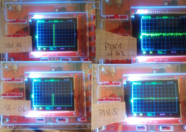
First I suggest that you check with the oscilloscope the voltages at pin 14 of U2, then between D3 and Q5. With a noise signal at the input (max range +/-4V) and the jumper on LOG check the signal at pin 1 of U2
_________________
Yves |
|
|
Back to top
|
|
|
Samuxx
Joined: Aug 24, 2016
Posts: 6
Location: Munich
|
| Posted: Fri Sep 09, 2016 4:00 am Post subject:
|
|
|
| So I tried to measure 14 of U2.. Nothing. I found out that I get signal (a clean square) at the 'left' side of c4 but nothing on the other. I tried 1n and 10n now for c4. |
|
|
Back to top
|
|
|
yusynth
Joined: Nov 24, 2005
Posts: 1314
Location: France
|
| Posted: Fri Sep 09, 2016 4:27 am Post subject:
|
|
|
On the other side of C4 you must see a brief positive spike (1 to 3 ms). If this is not the case check there is no short cut to the ground at the junction of C4 D2 and R11. Check that D2 is not in short-cut.
_________________
Yves |
|
|
Back to top
|
|
|
Samuxx
Joined: Aug 24, 2016
Posts: 6
Location: Munich
|
|
|
Back to top
|
|
|
yusynth
Joined: Nov 24, 2005
Posts: 1314
Location: France
|
| Posted: Sun Sep 25, 2016 5:59 am Post subject:
|
|
|
All your scope snapshots look OK to me. What bothers me is the amplitude of the noise signal you input in the circuit, merely 1Vpp, I would expect something bigger like 5 to 8Vpp.
_________________
Yves |
|
|
Back to top
|
|
|
Samuxx
Joined: Aug 24, 2016
Posts: 6
Location: Munich
|
| Posted: Sun Sep 25, 2016 10:09 am Post subject:
|
|
|
I checked everything again, and for some reason it finally works. I have no idea why.
Thank you very much for your support. It seems my first rack, filled with Yusynth modules, is finished.  It took me one year. It took me one year. |
|
|
Back to top
|
|
|
yusynth
Joined: Nov 24, 2005
Posts: 1314
Location: France
|
| Posted: Sun Sep 25, 2016 11:57 am Post subject:
|
|
|
If so (not working then suddenly working) check for a bad solder or a loose-contact...
_________________
Yves |
|
|
Back to top
|
|
|
|

 Forum index » DIY Hardware and Software » YuSynth