| Author |
Message |
kudamm99
Joined: Mar 08, 2014
Posts: 7
Location: Dayton, Ohio
|
 Posted: Sat Feb 03, 2018 3:49 pm Post subject:
Sync pulse from LED? Posted: Sat Feb 03, 2018 3:49 pm Post subject:
Sync pulse from LED?
Subject description: Can I hack a tap tempo button to provide sync in/out? |
  |
|
| I'm curious to know if there's a way to get Korg-style sync I/O via the tap tempo button and LED on my Akai MPK Mini MkII. That way the arpeggiator could potentially transmit sync or slave to external gear. Thanks. |
|
|
Back to top
|
|
 |
PHOBoS

Joined: Jan 14, 2010
Posts: 5884
Location: Moon Base
Audio files: 709
|
| Posted: Sat Feb 03, 2018 4:27 pm Post subject:
|
|
|
It might be possible but I can't tell without a schematic of the thing. There is a chance the LED is multiplexed which means it
is actually flashing very fast when on which could make it a bit tricky. An optocoupler in series with the LED might be a safe
way to tap into the signal without any chance of damaging the MPK. A vactrol might be even better because of the slow responce
of the LDR which could solve problems if the LED is indeed multiplexed. Of course you'd need some extra circuitry to turn it
into a useful signal.
_________________
"My perf, it's full of holes!"
http://phobos.000space.com/
SoundCloud BandCamp MixCloud Stickney Synthyards Captain Collider Twitch YouTube
Last edited by PHOBoS on Sat Feb 03, 2018 5:45 pm; edited 2 times in total |
|
|
Back to top
|
|
|
kudamm99
Joined: Mar 08, 2014
Posts: 7
Location: Dayton, Ohio
|
| Posted: Sat Feb 03, 2018 5:08 pm Post subject:
|
|
|
| Cool, thanks. I just got a bunch of LDRs to make that $3 low pass gate. I'll try working something up. |
|
|
Back to top
|
|
|
kudamm99
Joined: Mar 08, 2014
Posts: 7
Location: Dayton, Ohio
|
|
|
Back to top
|
|
|
PHOBoS
Joined: Jan 14, 2010
Posts: 5884
Location: Moon Base
Audio files: 709
|
| Posted: Mon Feb 05, 2018 5:04 pm Post subject:
|
|
|
I'd probably put the LED in series but this is easier to do and might even work better. It depends on the MK circuit that's driving the LED.
It could also be that the LED has a higher voltage drop than the one you are adding in which case it might not light up anymore.
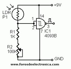
For the circuit I would make a voltage divider with the LDR and a resistor (trimpot might be very convenient) and feed that into a
schmitt trigger. You could make that with some transistors but I would use a CD4093 or CD40106. This will guarantee a very clean
(square) output. I'd also put a resistor (1K) in series with the output as a protection against possible shorts though with the
circuit you've drawn that's probably not necessary. (depending on LDR resistance). Just try it and see how it works for you.
_________________
"My perf, it's full of holes!"
http://phobos.000space.com/
SoundCloud BandCamp MixCloud Stickney Synthyards Captain Collider Twitch YouTube |
|
|
Back to top
|
|
|
blue hell
Site Admin

Joined: Apr 03, 2004
Posts: 24537
Location: The Netherlands, Enschede
Audio files: 299
G2 patch files: 320
|
| Posted: Tue Feb 06, 2018 6:27 am Post subject:
|
|
|
| PHOBoS wrote: | For the circuit I would make a voltage divider with the LDR and a resistor (trimpot might be very convenient) and feed that into a
schmitt trigger. |
As is, the circuit will not work as there is nothing to discharge the 10 µF capacitor (except maybe for an externally connected resistor on the output, but that would give ill defined behaviour), so once it is fully loaded nothing further will happen.
So at the very least it will need some load. Apart from that 10 µF seems a bit large with the resistance range an LDR can have.
But anyway, I'd follow PHOBoS' suggestion.
_________________
Jan
also .. could someone please turn down the thermostat a bit.
 |
|
|
Back to top
|
|
|
kudamm99
Joined: Mar 08, 2014
Posts: 7
Location: Dayton, Ohio
|
|
|
Back to top
|
|
|
PHOBoS
Joined: Jan 14, 2010
Posts: 5884
Location: Moon Base
Audio files: 709
|
|
|
Back to top
|
|
|
kudamm99
Joined: Mar 08, 2014
Posts: 7
Location: Dayton, Ohio
|
| Posted: Sun Feb 11, 2018 5:42 pm Post subject:
|
|
|
| Great, thanks so much for your help! |
|
|
Back to top
|
|
|
|

 Forum index » DIY Hardware and Software » Circuit Bending