| Author |
Message |
gasboss775

Joined: Jan 02, 2016
Posts: 217
Location: Scotland
|
|
|
Back to top
|
|
 |
JovianPyx

Joined: Nov 20, 2007
Posts: 1988
Location: West Red Spot, Jupiter
Audio files: 224
|
 Posted: Sat Feb 03, 2018 1:10 pm Post subject: Posted: Sat Feb 03, 2018 1:10 pm Post subject:
|
  |
|
If you've worked only with expo CV then you wouldn't have seen this current source - because it's linear and not expo. This means that if you use an expo CV to control the filter's cutoff, it won't behave the same way as what you're accustomed to.
Linear is also called hertz-per-volt or Hz/volt. Not sure if this filter will self oscillate - I'll assume it does. If you try to control the pitch of it (in self osc) the frequency will not track as expected. With linear - each doubling of the CV voltage will raise the frequency by one octave.
_________________
FPGA, dsPIC and Fatman Synth Stuff
Time flies like a banana.
Fruit flies when you're having fun.
BTW, Do these genes make my ass look fat?
corruptio optimi pessima
|
|
|
Back to top
|
|
|
gasboss775
Joined: Jan 02, 2016
Posts: 217
Location: Scotland
|
| Posted: Tue Mar 06, 2018 10:08 am Post subject:
|
|
|
| JovianPyx wrote: | If you've worked only with expo CV then you wouldn't have seen this current source - because it's linear and not expo. This means that if you use an expo CV to control the filter's cutoff, it won't behave the same way as what you're accustomed to.
Linear is also called hertz-per-volt or Hz/volt. Not sure if this filter will self oscillate - I'll assume it does. If you try to control the pitch of it (in self osc) the frequency will not track as expected. With linear - each doubling of the CV voltage will raise the frequency by one octave. |
Thanks JovianPix, but I really need to know the actual mechanics of how this circuit actually does what it does. Can you or anyone else elaborate please? |
|
|
Back to top
|
|
|
JovianPyx
Joined: Nov 20, 2007
Posts: 1988
Location: West Red Spot, Jupiter
Audio files: 224
|
| Posted: Tue Mar 06, 2018 10:59 am Post subject:
|
|
|
In the image below, there are 3 different ways to do linear current sources.
They all work in a similar way.
The resistor labled "I" is your load, such as an OTA. Note that in this case, the bottom end of resistor I is connected to -V. This emulates the reference that an OTA uses for Iabc.
The - input of the opamp is a summing node and because the + input is grounded, the summing node has a voltage of zero. The current flowing into the - input (which remains at ground potential) is copied via the feedback transistor, but will be opposite polarity such that the two currents (input and feedback) cancel each other out to maintain the summing node voltage of zero. Note that whatever current comes from the CV input is the same current supplied to resistor I. Be careful here, using an OTA requires the Iabc current be limited to no more than 20 mA (otherwise the OTA will blow).
When a voltage is applied via the CV input, the opamp output will force the summing node to remain at zero volts. As the voltage increases via the CV input resistor (fixed), the opamp output will go more and more negative to maintain the summing node at zero volts. In doing this, the darlington transistor is turn on more and more, opening the collector circuit which is supplying current to the resistor I. The circuit sources current from a potential of zero volts (through the darlington) to -V.
The main difference between the current source I show and the one in the schematic you supplied is the use of a darlington pair. This greatly reduces the error that is caused by some of the current flowing through the base-emitter junction of the pass transistor. This is because the darlington pair has much higher gain than a single transistor. The circuit on the right uses a MOSFET which reduces the error even further because there is virtually zero current flow from it's gate to source terminals.
| Description: |
|
| Filesize: |
7.59 KB |
| Viewed: |
492 Time(s) |
| This image has been reduced to fit the page. Click on it to enlarge. |
|
_________________
FPGA, dsPIC and Fatman Synth Stuff
Time flies like a banana.
Fruit flies when you're having fun.
BTW, Do these genes make my ass look fat?
corruptio optimi pessima
|
|
|
Back to top
|
|
|
gasboss775
Joined: Jan 02, 2016
Posts: 217
Location: Scotland
|
| Posted: Wed Mar 07, 2018 1:52 pm Post subject:
|
|
|
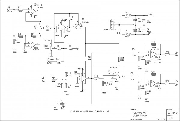
| JovianPyx , I get how the circuit's that you posted work. However in the Polivox circuit the base is connected to the inverting (-) input of the opamp and the emitter to the output of the opamp, I cant see how this could work the same way, do you think this is an error in the schematic? |
|
|
Back to top
|
|
|
JovianPyx
Joined: Nov 20, 2007
Posts: 1988
Location: West Red Spot, Jupiter
Audio files: 224
|
| Posted: Wed Mar 07, 2018 2:08 pm Post subject:
|
|
|
Yes, looking at the schematic again I do see what you mean.
What I see is that instead of the current coming from the summing node through the collector circuit, it appears to come from the opamp output through the collector-emitter circuit. I can't say for sure if it will work that way, but perhaps it does but not as a truly linear current source. Also, the way the base-emitter is biased, because there's no series base resistor, it looks like it could be possible to blow the transistor - however, there's that 3K shunt resistor which may protect the transistor. It could be that this arrangement is not linear, but also not expo, but it may be close to expo enough to help the filter track better?
As to "is there an error", I believe there is not. I just looked at another drawing of the same schematic and it is wired the same way. So I think that it is a non-linear / non-expo current source. The docs I found don't reveal much in terms of how it works.
_________________
FPGA, dsPIC and Fatman Synth Stuff
Time flies like a banana.
Fruit flies when you're having fun.
BTW, Do these genes make my ass look fat?
corruptio optimi pessima
|
|
|
Back to top
|
|
|
gasboss775
Joined: Jan 02, 2016
Posts: 217
Location: Scotland
|
| Posted: Wed Mar 07, 2018 3:13 pm Post subject:
|
|
|
| Thanks for your thoughts on this. I think I shall breadboard the circuit in order to get a better idea of what's going on here and to try and chart the relationship between input voltage and output current. |
|
|
Back to top
|
|
|
JovianPyx
Joined: Nov 20, 2007
Posts: 1988
Location: West Red Spot, Jupiter
Audio files: 224
|
| Posted: Wed Mar 07, 2018 3:26 pm Post subject:
|
|
|
That's what I'd try - at least you'll have the filter 
I'll be interested to see what comes out of that.
_________________
FPGA, dsPIC and Fatman Synth Stuff
Time flies like a banana.
Fruit flies when you're having fun.
BTW, Do these genes make my ass look fat?
corruptio optimi pessima
|
|
|
Back to top
|
|
|
gdavis
Joined: Feb 27, 2013
Posts: 359
Location: San Diego
Audio files: 1
|
| Posted: Fri Mar 09, 2018 6:58 pm Post subject:
|
|
|
| JovianPyx wrote: | Yes, looking at the schematic again I do see what you mean.
What I see is that instead of the current coming from the summing node through the collector circuit, it appears to come from the opamp output through the collector-emitter circuit. I can't say for sure if it will work that way, but perhaps it does but not as a truly linear current source. Also, the way the base-emitter is biased, because there's no series base resistor, it looks like it could be possible to blow the transistor - however, there's that 3K shunt resistor which may protect the transistor. It could be that this arrangement is not linear, but also not expo, but it may be close to expo enough to help the filter track better?
As to "is there an error", I believe there is not. I just looked at another drawing of the same schematic and it is wired the same way. So I think that it is a non-linear / non-expo current source. The docs I found don't reveal much in terms of how it works. |
The opamp is basically fixing Vbe to .06 * CV input (simplify by ignoring all the summing and buffering and just assume a single CV input). At this small Vbe, according to the Ebors-Moll model the current through the base is negligible compared to the current through R5 and R6. It's not relying on a base resistor to limit the current because the supplied Vbe is so limited.
I'm not familiar with the filter but I suspect Q1 is biased in a range that will respond exponentially to the CV input and provide the desired current to the UA776's, it's just not temperature stabilized with two matching transistors. Our ears aren't sensitive enough to hear the variation in cutoff frequency, it would only be noticeable if the filter were self-oscillating.
_________________
My synth build blog: http://gndsynth.blogspot.com/ |
|
|
Back to top
|
|
|
elektrouwe
Joined: May 27, 2012
Posts: 147
Location: Germany
|
| Posted: Sat Mar 10, 2018 3:30 am Post subject:
|
|
|
with RV1 you can morph between a positive and an inverted (ADSR)envelope .
RV2 is the basic cutoff freq. setting.
U2 with Q1 are a non temp. compensated inverting current sink, that pull down the current control inputs of the 2 UA776 when +CV rises.
BTW redesign:
If you want to replace the obsolete UA776 with an LM13700, control current direction is inverted:
RV2 and R7 must go to -15V, Q1 is a PNP then an R9 with J3 must be shifted to -in of U1B instead of U2. Of course the signal path requires also changes.. |
|
|
Back to top
|
|
|
JovianPyx
Joined: Nov 20, 2007
Posts: 1988
Location: West Red Spot, Jupiter
Audio files: 224
|
| Posted: Fri Mar 16, 2018 7:34 am Post subject:
|
|
|
Interesting...
Is this current source also used in polivoks VCO?
_________________
FPGA, dsPIC and Fatman Synth Stuff
Time flies like a banana.
Fruit flies when you're having fun.
BTW, Do these genes make my ass look fat?
corruptio optimi pessima
|
|
|
Back to top
|
|
|
elektrouwe
Joined: May 27, 2012
Posts: 147
Location: Germany
|
| Posted: Fri Mar 16, 2018 1:14 pm Post subject:
|
|
|
| JovianPyx wrote: | | Is this current source also used in polivoks VCO? |
no, a single transistor has a strong temperature drift; useless for VCOs |
|
|
Back to top
|
|
|
gasboss775
Joined: Jan 02, 2016
Posts: 217
Location: Scotland
|
| Posted: Thu Apr 08, 2021 12:02 pm Post subject:
|
|
|
I ran a simulation of this circuit just now and it does seem to follow an approximate exponential response. With zero input the circuit sinks only around 1.3uA, with all inputs full on about 20mA. It doesn't follow the 1v per octave characteristic, but is very definitely NOT a linear voltage controlled current sink.
As suggested earlier, it seems that the characteristic curve lies somewhere between linear and exponential |
|
|
Back to top
|
|
|
|

 Forum index » DIY Hardware and Software