| Author |
Message |
romaindegode

Joined: Feb 28, 2019
Posts: 26
Location: France.
|
 Posted: Mon Mar 11, 2019 5:17 pm Post subject: Posted: Mon Mar 11, 2019 5:17 pm Post subject:
 VCA : trimmer A1 balance & A3 offset null not responding VCA : trimmer A1 balance & A3 offset null not responding |
  |
|
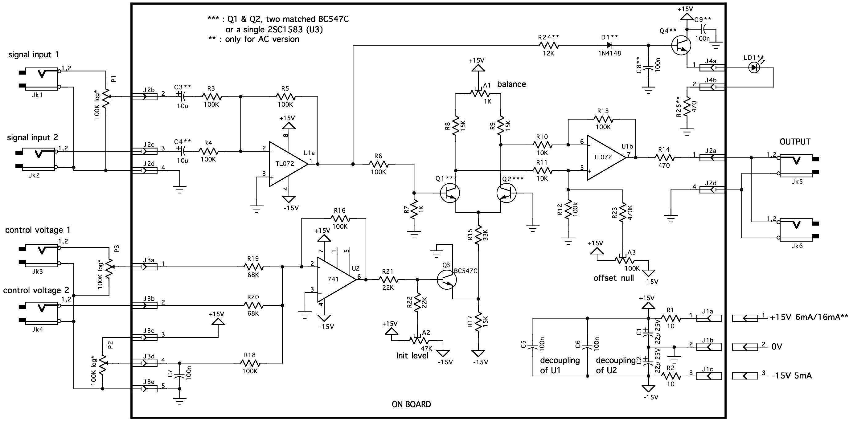
Schematics :

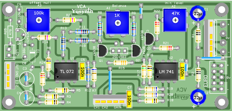
Board :

Hi,
I have had some success so far with 2 vco, 2 ADSR, Minimoog / EMS filter, dual mixer, sample&hold noise and a ACX midi2cv but those 2 bloody vca are making me crazy.
They work well, cv responding is good but the sinewave is not moving on the scope when i play with A1 and A3.
A2 init level works.
The VCA module was my first yusynth module attempt so i can say that i checked for error components values and their continuity with the tracks 50 times. Each little part of the schematics have been checked for continuity on the paper. Same for wiring.
Voltage changes till U1 when i play with A1 but the sinewave doesn't move at all on the scope. The sinewave from the vco on the first channhel of the scope is almost symmetrical with the vca sinewave but still... trimmers are not working
U1 & U2 have been replaced
Q1 & Q2 were picked in the same selection i've used for my minimoog filter so i dont suspect wrong matching.
I use 25 turn trimmers . I tried a 1turn for A3 on one vca but same problem (Yves said that 10turn is better than 1 turn)
I must do something wrong because i have exactly the same problem for both of my vca's. But i 'm totally missing it...
Hope my english is clear
Thanks for your help  |
|
|
Back to top
|
|
 |
ixtern
Joined: Jun 25, 2018
Posts: 145
Location: Poland
|
 Posted: Wed Mar 13, 2019 2:34 am Post subject:
Re: VCA : trimmer A1 balance & A3 offset null not responding Posted: Wed Mar 13, 2019 2:34 am Post subject:
Re: VCA : trimmer A1 balance & A3 offset null not responding |
  |
|
| romaindegode wrote: | Schematics :
I must do something wrong because i have exactly the same problem for both of my vca's. But i 'm totally missing it...
|
Looking at the schematic it seems that you can block VCA from working setting P2 and A2 into wrong positions.
Set A1 and A3 in the middle positions. Set P2 slider to the ground (0V). Then U2 output should be at 0V too.
Then set A2 slider to the minus voltage (-4...-5V) and check voltages at the transistors emitters. At Q1/Q2 emitters it should be about -0.7V, at Q3 emitter it should be about 0.7V less than at A2 slider.
Output of U1a should be 0V.
Check voltages at Q1 and Q2 collectors - should be the same, and lower than +15V and higher than 0V. If not, change A2 slider position slightly than measure again. Try set collectors voltages to about +7V.
If voltages at Q1 Q2 collectors are not the same, correct it with A1, if the same - set A3 to get 0V on U1b output.
If all above is OK, check circuit with sine signal (for the start reduce to 1V p-p max by P1).
Changing P2 position may require A2 correction. Do it by small steps. |
|
|
Back to top
|
|
 |
romaindegode

Joined: Feb 28, 2019
Posts: 26
Location: France.
|
 Posted: Thu Mar 14, 2019 11:43 am Post subject: Posted: Thu Mar 14, 2019 11:43 am Post subject:
|
  |
|
thanks a lot for your answer.
I followed strictly your instructions and here are my measurements :
With P2 to ground and -4,9V on A2
Q1/Q2 emitters : -0,55V
Q3 emitters : -3,1V
U1a out : 0V
U2a out : 0V
Q1/Q2 collectors : 12,25V
I'm able to put 0V on U1b out with A3
Same to egalize Q1/Q2 emitters with A1
But A1 and A3 don't have any effect on the sinewave on the scope
Also in order to remove sound leak when the vca is close, i have to set A2 in such a way that the sinewave coming from the vco become less when i open the vca with cv (1v less on the negative rail)
Like this :

The small sinewave is the one coming from the vco
And this is what happen if i put P2 at maximum :
 |
|
|
Back to top
|
|
 |
ixtern
Joined: Jun 25, 2018
Posts: 145
Location: Poland
|
 Posted: Thu Mar 14, 2019 1:26 pm Post subject: Posted: Thu Mar 14, 2019 1:26 pm Post subject:
|
  |
|
| romaindegode wrote: | thanks a lot for your answer.
I followed strictly your instructions and here are my measurements :
With P2 to ground and -4,9V on A2
Q1/Q2 emitters : -0,55V
Q3 emitters : -3,1V
U1a out : 0V
U2a out : 0V
Q1/Q2 collectors : 12,25V
I'm able to put 0V on U1b out with A3
Same to egalize Q1/Q2 emitters with A1
But A1 and A3 don't have any effect on the sinewave on the scope
Also in order to remove sound leak when the vca is close, i have to set A2 in such a way that the sinewave coming from the vco become less when i open the vca with cv (1v less on the negative rail)
Like this :
...
The small sinewave is the one coming from the vco
And this is what happen if i put P2 at maximum :
...
|
I am not sure what are you expecting. A3 has no effect on the output amplitude, it is only shifting output up and down in DC domain. If by accident you have set AC coupling for oscilloscope input, you will see no change in the signal.
A1 should also has small effect. Look at the values: A1 in half is 0.5 kOhm. It goes down to Q1 Q2 collectors by 15 kOhms resistors. So 0.5 kOhm change (max to one side) is about 1/30 of total collector resistance. A1 is only for "polishing" VCA work, not for substantial change of signal.
Try to set A2 such way that voltage on Q1 and Q2 collectors is near +15V (but little less). Then play with input signal and P3 control voltage. If Q1 and Q2 are matched and U1b has small offset, then no need to change A1 and A3 at all. Sinus at Q1 Q2 collectors should be not bigger than 1V p-p at max. |
|
|
Back to top
|
|
 |
JovianPyx

Joined: Nov 20, 2007
Posts: 1988
Location: West Red Spot, Jupiter
Audio files: 224
|
 Posted: Thu Mar 14, 2019 1:28 pm Post subject: Posted: Thu Mar 14, 2019 1:28 pm Post subject:
|
  |
|
I would power it down and then check ohms from the wiper to each side turning the trimmer and seeing that the ohms change when you turn it. Do that for both A1 and A2 trimmers. It's possible that some kind of dirt/garbage/corrosion or even oil was on the trimmer leads when you soldered. Very often, such things happen because of bad solder connections and the fix is usually just reflowing the solder on those connections (all three pins of the trimmer). That's just a guess from your description of the symptom, it could also be that the trimmer wiper isn't touching the resistor surface of the trimmer. If that is the case, the ohmmeter might show open circuit when you test from wiper to either side. The fix for that is to get new trimmers.
_________________
FPGA, dsPIC and Fatman Synth Stuff
Time flies like a banana.
Fruit flies when you're having fun.
BTW, Do these genes make my ass look fat?
corruptio optimi pessima
|
|
|
Back to top
|
|
 |
romaindegode

Joined: Feb 28, 2019
Posts: 26
Location: France.
|
 Posted: Thu Mar 14, 2019 2:24 pm Post subject: Posted: Thu Mar 14, 2019 2:24 pm Post subject:
|
  |
|
 sorry, it was that, i was on ac coupling all this time and i never thought the problem could come from there. sorry, it was that, i was on ac coupling all this time and i never thought the problem could come from there.
Actually, i didn't know it could make a difference, i guess i have to take some time to really understand how works an oscilloscope
thanks guys for your help |
|
|
Back to top
|
|
 |
JovianPyx

Joined: Nov 20, 2007
Posts: 1988
Location: West Red Spot, Jupiter
Audio files: 224
|
 Posted: Thu Mar 14, 2019 3:41 pm Post subject: Posted: Thu Mar 14, 2019 3:41 pm Post subject:
|
  |
|
Oh yes... On AC both a DMM and an oscope will read zero volts for a DC signal because there is an internal DC blocking capacitor. When you first touch the probe to the circuit the oscope or DMM will show just a jump and then go to zero.
It's good to learn stuff though, eh?    
_________________
FPGA, dsPIC and Fatman Synth Stuff
Time flies like a banana.
Fruit flies when you're having fun.
BTW, Do these genes make my ass look fat?
corruptio optimi pessima
|
|
|
Back to top
|
|
 |
romaindegode

Joined: Feb 28, 2019
Posts: 26
Location: France.
|
 Posted: Thu Mar 14, 2019 4:53 pm Post subject: Posted: Thu Mar 14, 2019 4:53 pm Post subject:
|
  |
|
Oh yes I really enjoy this adventure. I just wish to have more time to building, making music and learn the theory...or leaving my job.......  |
|
|
Back to top
|
|
 |
PiercedFaceMan

Joined: Jun 11, 2020
Posts: 8
Location: Reading, United Kingdom.
|
 Posted: Wed Feb 10, 2021 12:29 pm Post subject:
Same same.. Posted: Wed Feb 10, 2021 12:29 pm Post subject:
Same same.. |
  |
|
Hah!
I had this same problem for a week before I managed to find this post.
Thank Moog. |
|
|
Back to top
|
|
 |
|

