| Author |
Message |
bandwidth
Joined: Jan 29, 2018
Posts: 4
Location: US
|
 Posted: Mon Jan 29, 2018 1:07 pm Post subject:
LFO v2 Issues Posted: Mon Jan 29, 2018 1:07 pm Post subject:
LFO v2 Issues |
  |
|
Hi everybody, I built a VC LFO v2 and I am having some problems with it. Here is what I am seeing:
At the sine and rectangle outputs: 10vpp, -5 to +5v
At the saw and triangle outputs: 18vpp, -9 to +9v
At U2, pin 7: 10vpp ramp, 0 to +10v
At U2, pin 1: 18vpp saw, -8 to +10v with range switch at x1
At U2, pin 1: 15vpp saw, -10 to +5v with range switch at x.1
I've read through the pages here checking out other peoples' problems and the recommendations made. Much of the circuit seems to be working.
Thanks for any help. |
|
|
Back to top
|
|
 |
gabbagabi

Joined: Nov 29, 2008
Posts: 652
Location: Berlin by n8
Audio files: 23
|
| Posted: Tue Jan 30, 2018 11:18 am Post subject:
|
|
|
hello and  to the forum to the forum
At U2, pin 7: 10vpp ramp, 0 to +10v seems to be ok, as far as i remember the 555 switches at 66% supply voltage.
this signal then goes to U2A and will then be amplyfied two times, which gives theoretically 0 to +20V, which is to much and ur measurements at At U2, pin 1 seems to confirm that
for that reason i would try to change R17 to 100k
cheers, gabbagabi |
|
|
Back to top
|
|
|
bandwidth
Joined: Jan 29, 2018
Posts: 4
Location: US
|
| Posted: Tue Jan 30, 2018 4:13 pm Post subject:
|
|
|
Hello g.gabba and thanks for the welcome and assistance!
After reading your reply, I did this: changed R35, the feedback resistor for the saw op amp U2d, to 51k ohms. This halved the signal and I now have a 10vpp saw.
I understand your reasoning for the change of R17 to 100k, but was worried that the saw and triangle would at the proper voltage, but the sine and rectangle would be too low.
Since I have the version 2 LFO, I have a free op amp onboard, and I'm thinking I'll try this to fix the triangle:
Lift the side of R25 connecting it to U3c, pin 8.
Install a jumper from R25’s free pad to the SEL connection.
Install a 100K ohm resistor at R31.
Remove jumper at R34 and install a 51k ohm resistor at R34.
Install a jumper between R32 connection to U3a, pin 1 and the lifted end of R25.
Hope like heck that gets me a 10vpp triangle! 
Thanks again, I'll report back after I've done this. |
|
|
Back to top
|
|
|
gabbagabi
Joined: Nov 29, 2008
Posts: 652
Location: Berlin by n8
Audio files: 23
|
| Posted: Tue Jan 30, 2018 11:39 pm Post subject:
|
|
|
the tri and sine waveshaper expecting a well centered +/-5V saw (or ramp) wave as input
to archive that u should lower R17 to 100k, the centering u do then with the saw bias pots, the saw output is then automaticly right
edit: the tri waveshaper (aka precisicion rectifier) would of course also work with higher voltages
edit2: there are two R17 one at the tri waveshaper IC3C (with the 1n Cap) and another R17 at IC2A (with the 120p Cap) - i was talking about R17 at IC2A (with the 120p Cap) the other one should stay at 200k to produce proper SIN TRI Waves |
|
|
Back to top
|
|
|
bandwidth
Joined: Jan 29, 2018
Posts: 4
Location: US
|
| Posted: Wed Jan 31, 2018 8:30 pm Post subject:
|
|
|
 Alright! My goofy little scheme worked. I now have a 10vpp triangle - it is inverted, of course - but it is 10vpp. I was able to get the LFO through the tuning and trimming steps and it is installed in the synth. It seems to be working properly. Alright! My goofy little scheme worked. I now have a 10vpp triangle - it is inverted, of course - but it is 10vpp. I was able to get the LFO through the tuning and trimming steps and it is installed in the synth. It seems to be working properly.
Thank you g.gabba for your thoughts and input. It would have certainly been easier to replace just the R17 resistor, but I have a long history of doing things the hard way! |
|
|
Back to top
|
|
|
gabbagabi
Joined: Nov 29, 2008
Posts: 652
Location: Berlin by n8
Audio files: 23
|
| Posted: Thu Feb 01, 2018 10:48 am Post subject:
|
|
|

please feel free to to do what ever u want with your circuits, there are no laws to say what u have to do, may this is the reason why i like sdiy so much
you set the restrictions yourself eg by going in to a fixed format like eurorack or motm..
anyway i did not evaluate ur whole workaround the tri and saw section seems to be ok now, what is with the PWM?
cheers
gabbagabi |
|
|
Back to top
|
|
|
bandwidth
Joined: Jan 29, 2018
Posts: 4
Location: US
|
| Posted: Thu Feb 01, 2018 12:13 pm Post subject:
|
|
|
| Thanks again for your help and ideas! The PWM, FM circuit and Sync In all worked from the beginning, well, once I got it trimmed sufficiently. The saw and triangle amplitudes were the biggest problems. They were just challenges to be met and overcome! |
|
|
Back to top
|
|
|
romaindegode

Joined: Feb 28, 2019
Posts: 26
Location: France.
|
| Posted: Sat Mar 30, 2019 6:34 am Post subject:
|
|
|
Replacing R17 to 100K was a good help ! My LFO works now normally
 |
|
|
Back to top
|
|
|
romaindegode
Joined: Feb 28, 2019
Posts: 26
Location: France.
|
| Posted: Mon Apr 08, 2019 9:57 am Post subject:
|
|
|
Yves told me that 200k is the correct value for r17.
We made the same mistake somewhere before r17...
Don't know if it is change something though, my Lfo seems to work correctly |
|
|
Back to top
|
|
|
gabbagabi
Joined: Nov 29, 2008
Posts: 652
Location: Berlin by n8
Audio files: 23
|
| Posted: Mon Apr 08, 2019 10:36 am Post subject:
|
|
|
| mind that there are two R17 |
|
|
Back to top
|
|
|
romaindegode
Joined: Feb 28, 2019
Posts: 26
Location: France.
|
| Posted: Tue Apr 09, 2019 6:07 am Post subject:
|
|
|
Yves told me that the LFO saw/triangle was suppose to have 20vpp when he conceived this module in the beginning.
100K for the real R17 is correct if we expect 10vpp for triangle/saw. The other R17 is actually R23.
Corrections will be done for both R17/R23 designations and for the trim process
Thanks g.gabba for your help !  |
|
|
Back to top
|
|
|
gabbagabi
Joined: Nov 29, 2008
Posts: 652
Location: Berlin by n8
Audio files: 23
|
| Posted: Tue Apr 09, 2019 6:22 am Post subject:
|
|
|
pleasure,
(damn it looks like i managed to to say something usefull  ) )
cu
|
|
|
Back to top
|
|
|
hububalli
Joined: Feb 15, 2014
Posts: 41
Location: UK
|
| Posted: Mon May 13, 2019 12:30 pm Post subject:
|
|
|
I am having some trouble with my LFO V2 as well. I have changed R17 for 100k (The 120p cap R17) and which has reduced the output.
I am having a problem with the X 1.0 & X 0.1 switch. After flipping it over to X 0.1, it introduces an offset to the Tri and Saw outputs. Seems to be about -1.7 V.
This is roughly what I have now;
X 1.0
Tri 8 vpp
Saw 10 vpp
Sqr 9 vpp
Sine 8 vpp
X 0.1
Tri 6 vpp (with offset)
Saw 6 vpp
Sqr 9 vpp
Sine 7 vpp (with offset)
Any ideas?
Last edited by hububalli on Tue May 14, 2019 11:29 am; edited 1 time in total |
|
|
Back to top
|
|
|
gabbagabi
Joined: Nov 29, 2008
Posts: 652
Location: Berlin by n8
Audio files: 23
|
| Posted: Mon May 13, 2019 11:18 pm Post subject:
|
|
|
as far as i remember, there where two trimmers labled "SAW BIAS"
can you kill the offset with them? |
|
|
Back to top
|
|
|
hububalli
Joined: Feb 15, 2014
Posts: 41
Location: UK
|
| Posted: Tue May 14, 2019 11:29 am Post subject:
|
|
|
yes you are correct about the saw bias. I have used those to achieve balanced saw and square wave forms for X 0.1 and X 1.0.
The problem I am having is on the Tri and Sine outputs when using X 0.1. It is only for those two am I seeing the offset.
 |
|
|
Back to top
|
|
|
gabbagabi
Joined: Nov 29, 2008
Posts: 652
Location: Berlin by n8
Audio files: 23
|
| Posted: Sat May 18, 2019 3:53 am Post subject:
|
|
|
i have to apologize,
i did not read ur post in such detail as i should have,
sry
but i have no idea rigth now how that amplitude drop can can happen.
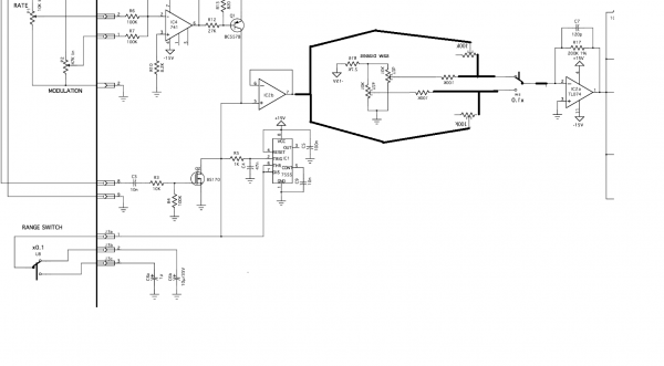
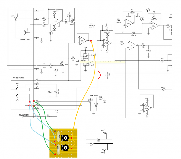
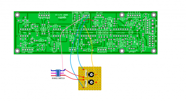
i only could offer an idea for a workaround, which i have attached.
This workaround would need you to solder out R14 and R15, solder in a bridge for R15, and a piece of Stripboard with two resistors (you could recycle R14 and R15) and two additional trimmer.
| Description: |
|
| Filesize: |
137.32 KB |
| Viewed: |
371 Time(s) |
| This image has been reduced to fit the page. Click on it to enlarge. |
|
| Description: |
|
| Filesize: |
260.99 KB |
| Viewed: |
380 Time(s) |
| This image has been reduced to fit the page. Click on it to enlarge. |
|
| Description: |
|
| Filesize: |
950.46 KB |
| Viewed: |
364 Time(s) |
| This image has been reduced to fit the page. Click on it to enlarge. |
|
|
|
|
Back to top
|
|
|
hububalli
Joined: Feb 15, 2014
Posts: 41
Location: UK
|
| Posted: Fri May 31, 2019 12:49 pm Post subject:
|
|
|
Had some time today so had a look at your suggestion. Am I right in thinking this will give me a way to adjust the gain of the signal from IC2 pin 7?
I wonder if this will have an effect on the offset that I am experiencing? The signal will be higher but it will still be offset by -1.7 V on X0.1 Sine and Triangle output.
Again, thanks for all your assistance g.gabba. |
|
|
Back to top
|
|
|
gabbagabi
Joined: Nov 29, 2008
Posts: 652
Location: Berlin by n8
Audio files: 23
|
| Posted: Sat Jun 01, 2019 9:52 am Post subject:
|
|
|
np it was a welcome task to think about,
the idea is to give you controll of the gain AND the offset for both setting (0,1&1) independently, with minimal effort.
the offset you can still calibrate on the two trimmers on the pcb,
the gain on the daughter board.
off course if you change the gain you will also change the offset,
so you will need to trimm them "thogether"
gl |
|
|
Back to top
|
|
|
hububalli
Joined: Feb 15, 2014
Posts: 41
Location: UK
|
| Posted: Sat Jun 15, 2019 12:56 pm Post subject:
|
|
|
It works!
Had a chance this evening to have another go and the relationship between the trimmers on the PCB and daughter board started making more sense.
It was kind of like trimming a VCO, you have to overshoot the mark with trimmer A, then bring it back down with trimmer B. |
|
|
Back to top
|
|
|
gabbagabi
Joined: Nov 29, 2008
Posts: 652
Location: Berlin by n8
Audio files: 23
|
| Posted: Sun Jun 16, 2019 12:53 am Post subject:
|
|
|
| gläd to heär it wörks! |
|
|
Back to top
|
|
|
clarionut
Joined: Feb 05, 2021
Posts: 7
Location: Cambridge UK
|
| Posted: Thu Apr 04, 2024 1:23 am Post subject:
|
|
|
Resurrecting this thread because I had the same issue (DC offset on slow setting output) with my YuSynth LFOv2 and this clever fix was the only solution I could find online. It works perfectly - many thanks!
A quick additional note - you don't need to use two trimmers on the daughter board. Just use two 100k resistors for the 'fast' side and resistor + trimmer as shown for the 'slow' side.
Trim the LFO fast setting first using the fast Saw Bias trimmer to get a good triangle wave shape, followed by the Sine/Tri Symmetry trimmer to remove any DC offset. Switch to 'slow' and adjust iteratively using the slow Saw Bias and new Gain trimmers (they interact with each other) to get a good triangle wave with no DC offset. Don't touch the Sine/Tri Symmetry trimmer during this step. |
|
|
Back to top
|
|
|
gabbagabi
Joined: Nov 29, 2008
Posts: 652
Location: Berlin by n8
Audio files: 23
|
| Posted: Thu Apr 04, 2024 10:29 pm Post subject:
|
|
|
Yeah, Good news in the morning! THX! Regards
 |
|
|
Back to top
|
|
|
|

 Forum index » DIY Hardware and Software » YuSynth
