| Author |
Message |
Bodo1967
Joined: Aug 10, 2016
Posts: 15
Location: Germany
|
 Posted: Mon Sep 14, 2020 5:21 am Post subject:
Steiner VCF - strange self oscillation problem Posted: Mon Sep 14, 2020 5:21 am Post subject:
Steiner VCF - strange self oscillation problem |
  |
|
Hi,
I built the YuSynth Steiner filter (current version according to the web site).
Everything (all 4 modes, cutoff, resonance, cv...) works absolutely perfectly - except for one thing:
The filter does actually self oscillate when the resonance is cranked up sufficiently, but does so in a rather high frequency range (kHz), which hardly - if at all - responds to the cutoff pot and/or applied CV. Also, it rather looks trapezoidal than like a sine wave.
Any ideas?
Additional info:
- There is a difference concerning R22 between the schematic and the layout It's 220k in the schematic and 330k in the layout. I used 220k there.
- Increasing R18 (I used 4k7) in several steps to about 32k led to no improvement.
- The 2k trimmer (T2) also has no noticeable effect, but that may be a follow-up to the oscillation being somewhere out of a useful range. |
|
|
Back to top
|
|
 |
romaindegode

Joined: Feb 28, 2019
Posts: 26
Location: France.
|
| Posted: Mon Sep 14, 2020 11:58 am Post subject:
|
|
|
Hi
Did you used BC547? Matching pair was OK?
I'm asking that because you have no effect on T2 trim and Yves suggests that problems might happen with a bad matching
Did you try different values for R18? This resistor has to do with resonance range.
It would be nice if you could put some pictures of both side pcb
Also if you double checked wiring, you should triple check 😉 |
|
|
Back to top
|
|
|
Bodo1967
Joined: Aug 10, 2016
Posts: 15
Location: Germany
|
| Posted: Mon Sep 14, 2020 11:28 pm Post subject:
|
|
|
Hi,
thanks for your reply  ! !
| romaindegode wrote: | | Did you used BC547? Matching pair was OK? |
Yes and yes - and it was no problem at all to trim the CV bleedthrough to almost invisible and inaudible.
| romaindegode wrote: | | I'm asking that because you have no effect on T2 trim |
Argh, my bad. I correctly wrote "2k trimmer" (the other one is 1k), but that's T1 (near the edge of the board), not T2  . T2 is 1k and used for eliminating CV bleedthrough (in the center of the board). And that went flawlessly, as I wrote above. . T2 is 1k and used for eliminating CV bleedthrough (in the center of the board). And that went flawlessly, as I wrote above.
| romaindegode wrote: | | Did you try different values for R18? |
Yes, that's what I meant by "Increasing R18 (I used 4k7) in several steps to about 32k...". Those steps were 4k7; 2 * 4k7; 3 * 4k7; and 4k7 + 27k, meaning resistance values of 4k7, 9k4, 14k1 and 31k7 respectively.
| romaindegode wrote: | | It would be nice if you could put some pictures of both side pcb |
Sure (I made a KiCad layout of the PCB, which I of course triple checked before getting it manufactured). I'll check once more (including checking for accidental solder blobs and/or bad solder joints) and if I don't find any obvious mistake I'll post pictures.
| romaindegode wrote: | | Also if you double checked wiring, you should triple check 😉 |
Did that as well, but I doubt I made any mistakes here since everything else works as it should. |
|
|
Back to top
|
|
|
Bodo1967
Joined: Aug 10, 2016
Posts: 15
Location: Germany
|
| Posted: Sat Sep 19, 2020 12:32 pm Post subject:
|
|
|
| romaindegode wrote: | | It would be nice if you could put some pictures of both side pcb |
OK, here we go -
it seems I can't add more than 5 pics to one post, so I'll have to do it in two posts.
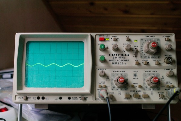
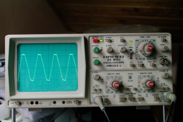
Oscilloscope pics are all taken with self oscillating filter. The first and last ones are from the output jack. Frequency at this point ranges from approximately 2.2 - 3.5 kHz, depending on the cutoff pot setting. The first TL074 I had put in returned a kind of trapezoid wave, whereas the second one is more or less a square wave.
The three in the middle taken on pin 5 of the IC. At lower cutoff settings the wave is a bit triangle-ish. It goes down in amplitude and turns into a sine wave at higher settings of the cutoff pot.
Edit: The preview showed the pics in different order - best look at them in inverted order  . .
| Description: |
| filter output after having swapped the TL047 |
|
| Filesize: |
370.38 KB |
| Viewed: |
354 Time(s) |
| This image has been reduced to fit the page. Click on it to enlarge. |

|
| Description: |
| same signal as before, but with Y scaling on the oscilloscope increased a bit |
|
| Filesize: |
387.69 KB |
| Viewed: |
336 Time(s) |
| This image has been reduced to fit the page. Click on it to enlarge. |

|
| Description: |
| pin 5 of the TL074 at higher cutoff setting |
|
| Filesize: |
388.23 KB |
| Viewed: |
327 Time(s) |
| This image has been reduced to fit the page. Click on it to enlarge. |
|
| Description: |
| pin 5 of the TL074 at low cutoff setting |
|
| Filesize: |
388.99 KB |
| Viewed: |
351 Time(s) |
| This image has been reduced to fit the page. Click on it to enlarge. |

|
| Description: |
|
| Filesize: |
386.38 KB |
| Viewed: |
355 Time(s) |
| This image has been reduced to fit the page. Click on it to enlarge. |
|
|
|
|
Back to top
|
|
|
Bodo1967
Joined: Aug 10, 2016
Posts: 15
Location: Germany
|
| Posted: Sat Sep 19, 2020 12:39 pm Post subject:
|
|
|
OK, and here's the PCB pics
| Description: |
| front side - pleace note I repalce the jumper near the upper egde (close to the manufacturer's code) with a cooper track |
|
| Filesize: |
397.96 KB |
| Viewed: |
359 Time(s) |
| This image has been reduced to fit the page. Click on it to enlarge. |

|
| Description: |
|
| Filesize: |
376.27 KB |
| Viewed: |
352 Time(s) |
| This image has been reduced to fit the page. Click on it to enlarge. |

|
| Description: |
|
| Filesize: |
395.95 KB |
| Viewed: |
340 Time(s) |
| This image has been reduced to fit the page. Click on it to enlarge. |

|
| Description: |
| back side, populated. I resoldered everything again today, and made sure there are no solder blobs. Didn't change anything though. |
|
| Filesize: |
379.93 KB |
| Viewed: |
347 Time(s) |
| This image has been reduced to fit the page. Click on it to enlarge. |

|
|
|
|
Back to top
|
|
|
|

 Forum index » DIY Hardware and Software » YuSynth


