| Author |
Message |
Ricko
Joined: Dec 25, 2007
Posts: 251
Location: Sydney, Australia
Audio files: 27
|
 Posted: Thu Oct 08, 2009 9:34 pm Post subject:
Encapsulated Realton Variaphon waveshaper circuit revealed! Posted: Thu Oct 08, 2009 9:34 pm Post subject:
Encapsulated Realton Variaphon waveshaper circuit revealed!
Subject description: Wind/brass instrument synthesis using dynamic fixed pulses |
  |
|
The videos of the Variophon being played (like the one on Matrix Synth) are amazing: obviously some of the realism comes from the breath noises that modulates the output, but the basic tone generation method is interesting. I found the description of the method on the Variaphon website isn't very clear. And the waveshaping circuits were encapsulated in resin, so no-one had reverse engineered it.
I've just found a newer paper on it which is pretty clear, by an academic (the son of one of the inventors?) http://www.chr-reuter.de/ViTa05_Oehler-Reuter-paper.pdf
Best of all, the paper has a circuit diagram for a prototype trumpet waveshaper they found. Pretty neat! I think the circuit is dependent on the components and signal level approaching rail levels for its distortion effects, like how people use a 3080 for tri->sine->square waveshaping by overdriving it.
In modular synth terms, the whole system is something like this:
VCO -> Monostable -> VCA -> Waveshaper + fixed filters -> VCA
Plus
breath -> LPF -> VCAs and Monostable PW
[Update:
Plus a "register" system that switches between different control values, based on CV ranges. (Of the three registers, the middle register would be 12, 15 or 18 semitones I guess.) This may include having a more complex monostable arrangement with a frequency divider, so that the middle register is single pulsed while the lower register is double pulsed.]
So at different levels of playing (pp to ff)
1) The formant shape shifts slightly due to slight pulse difference
2) The spectrum richness and high harmonic balance shifts due to distortion inside the wave shaper
3) The total volume is controlled by the final VCA.
The fixed filters are an HPF, BPF, HPF arrangement, not voltage controlled: the BPF just sets the lowest resonance (bell resonance) it seems. The dynamics and formants are mostly done using the pulse formation and waveshaping not the filters: contrast the 8 op-amps here with eg the JH fixed filter module [This is not a criticism!] I think these fixed filters are the op-amps shown at the top of the circuit diagram in the paper: one of the filter modules is brought out separately, I guess for front panel adjustment of mix.
Anyone who can provide an analysis of what is going on in the waveshaper (the bottom section), I'd love to know. It is some tangle of integrators/filters/squarers, yes?
[UPDATE: There is also a follow-up paper, giving information for the bassoon modules. http://doc.gold.ac.uk/~map01ra/dmrn/events/dmrn06/papers/oehler2006wind.pdf
The height does not vary, but the the pulse width is stepped according to the input CV into ranges that represent the three different registers: the same effect would presumably be happening for all reed, recorder and double reed instruments. So in the modular version, you'd have a non-linear stepping waveshaper on the input CV also being fed into the PW of the monostable.)
They are getting good milage from their research: the two papers are also combined in http://www.marcocosta.it/icmpc2006/pdfs/225.pdf with added info on breath noise: does this provide extra excitation of the waveshaper?
Oehler has even written a book (in German) on the whole subject.
There is the patent (out of date now) at http://www.freepatentsonline.com/4265157.pdf
This seems to have the basic idea, but is based on a mic input with frequency extraction, rather like the Extractorator idea I posted here earlier http://electro-music.com/forum/viewtopic.php?highlight=extractorator&t=33539 ]
Cheers
Rick
For a less elaborate (and not theory-based) version of a pulse waveshaper, see my BLIPPER http://extra.schematron.com/schematics/BLIP.JPG However, it is not dynamic at all. |
|
|
Back to top
|
|
 |
toppobrillo

Joined: Dec 10, 2005
Posts: 766
Location: oakland, ca
G2 patch files: 1
|
| Posted: Fri Oct 09, 2009 12:56 am Post subject:
|
|
|
| really cool thx rick! |
|
|
Back to top
|
|
|
StephenGiles
Joined: Apr 17, 2006
Posts: 507
Location: England
|
| Posted: Fri Oct 09, 2009 1:33 am Post subject:
|
|
|
| Is my eyes or is the trumpet shaper circuit unreadable? |
|
|
Back to top
|
|
|
Ricko
Joined: Dec 25, 2007
Posts: 251
Location: Sydney, Australia
Audio files: 27
|
| Posted: Fri Oct 09, 2009 2:08 am Post subject:
|
|
|
The diagram part values are almost illegible but the configuration is clear and the article is readable!
I don't think any fancy part values are used so the values can be figured out. (...Apart from the ??TCA746??? what is that? dual op-amp with built-in resistors?)
The most interesting part to me is the parallel C5 and R33. My stab is that they would shift various harmonics' phases (above 500Hz? what is the correct calculation to use?) and so give a different shape to be distorted at the next stage (if that is what is going on...)
Cheers
Rick |
|
|
Back to top
|
|
|
topcat
Joined: Feb 11, 2008
Posts: 9
Location: Oxford
|
| Posted: Mon Oct 12, 2009 4:10 am Post subject:
TCA 74x |
|
|
Could it be a TCA 740 dc controlled tone control?...
At first glance it looks the right fit...The TCA 730 and 740 appeared in some hifi and pro audio gear in the 80's
Enjoy
Tim
| Description: |
|

Download (listen) |
| Filename: |
TCA740.pdf |
| Filesize: |
413.91 KB |
| Downloaded: |
478 Time(s) |
| Description: |
|
Download (listen) |
| Filename: |
TCA730.pdf |
| Filesize: |
599.04 KB |
| Downloaded: |
466 Time(s) |
|
|
|
Back to top
|
|
|
Ricko
Joined: Dec 25, 2007
Posts: 251
Location: Sydney, Australia
Audio files: 27
|
| Posted: Mon Oct 12, 2009 8:07 am Post subject:
|
|
|
Yikes that is not so simple is it? I'll have to take back my comment on it being readable 
If the bottom row is tone control elements, it explains how the dynamic variation (shift to higher harmonics) happens: a much more active route than mere extra distortion.
So there must be another circuit for the dynamics that controls the tone control chip? (The SPICE simulation mustn't be up for modeling this, I guess, so they have hard coded a number or equation?) If they were hardcoded a setting, I would expect to see it.
I guess the thing to do would be to contact Herr Dr Reuter! |
|
|
Back to top
|
|
|
topcat
Joined: Feb 11, 2008
Posts: 9
Location: Oxford
|
| Posted: Mon Oct 12, 2009 1:55 pm Post subject:
It might be that simple |
|
|
Looks like a low pass filter followed by 'bass and treble' followed by two level controls driving formants....good idea to ask...the theory is interesting but the implementation looks simpler.....great use of the 'fixed formants' from the fixed pulse widths...a great trick ...think one of the Electronotes animators used a bunch of voltage controlled monostables......One thought the gain range from the second TCA doesn't appear to be enough to cover off the 'envelope'
Great stuff! |
|
|
Back to top
|
|
|
Ricko
Joined: Dec 25, 2007
Posts: 251
Location: Sydney, Australia
Audio files: 27
|
| Posted: Mon Oct 12, 2009 4:30 pm Post subject:
|
|
|
Yes, but I am kinda disappointed if much of the tone happens from conventional filters. I suppose 8 filter stages (4 dynamic) is a bit more sophisticated than the three stages + VCF that the ARP pro-soloist etc had. It would be interesting to see a filter plot to figure out how much they were contributing.
But the articles etc don't really mention the filters at all. Perhaps the trumpet has more requirements compared to reeds and pipes. |
|
|
Back to top
|
|
|
topcat
Joined: Feb 11, 2008
Posts: 9
Location: Oxford
|
| Posted: Fri Jul 04, 2014 10:31 am Post subject:
|
|
|
Hi Ricko,
Did you mange to contact the guy or get any more info?
tc |
|
|
Back to top
|
|
|
Ricko
Joined: Dec 25, 2007
Posts: 251
Location: Sydney, Australia
Audio files: 27
|
| Posted: Fri Oct 23, 2020 7:25 pm Post subject:
|
|
|
Updated URL for circuit diagram:
https://www.researchgate.net/publication/263228583_The_digital_pulse_forming_as_an_oldnew_sound_synthesis_principle
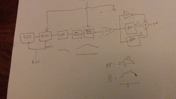
I have tried to reverse engineer the schematic fragment in my head, and there is a block diagram attached of my theory.
What seems to be going on is that the input pulses (which vary in height and width according to dynamics) are
1. low pass filtered (Sallen Key 12db .5Q ) at about 4.5kHz.
2. 6db High pass for some bass or DC removal by cap C2. Probably just DC removal.
3. a TCA740 stereo high/low tone control provide 2 pairs of voltage controlled seesaw potentiometers, arranged in series. Usually the TCA740 is used for stereo high/low Bandaxall tone controls, for bass and treble boost. Here, the high and low overlap, so you get a kind of mid boosting.
3a. The first is configured as a low boost-cut. However it is not at the standard point from the datasheets of 1k cutoff. Instead it is higher, more like 10k.
3b. The second is a high boost/cut. It presumably must use the same cv as 3a. And it again is not the standard 1k, but is lower, more like 600 Hz. So so response woukd be flat at 50%, 100% it would be louder with a boost betwen 600 and 10k (ie 2.5k peak), and at 25% it would be softer with a dip at 2.5k, and at 0% it would be softest. (I bet the Variophon trumpet only uses the 60 to 100%: cannot be seen in the schematic)
3c. The third is a VCA, going to the two formant filters 4
3b. The fourth is a VCA with going to the output. Because the signal goes through two vcas, this will gave an expo law response to envelope or adjustment, while the formants only are linear.
4. The output after the first VCA goes through two bandpass filters U11 and U12. U11 is at maybe about 1.2 to 4.3kHz, 2.5x boost. U12 is from 1.6 to 2.5kHz, higher boost.
So, assuming the expresion/breath/EF/ADSR is controlling the TCA740 CVs in a straight forward way:
* pp sounds go through the 4.5k Lpf and the two formant filters
* f sounds do too, but have the 2.5k boost too (which the formant filters will amplify too), and a little of the non-formant direct. The pulse width will be different (narrower and louder?) than the soft sounds.
* ff sounds will have more of the 2.5k boost and more of the non-formant sound. (Again the pulse width will be slightly different than the f sounds.)
So how does this fit into what the spectrums in the article show? In the article figure 8b, we do see that at pp most of the energy is between 700 and 2.5k, with a peak around 1.5k.
And ff adds more harmonics between 3k and 7k, and below 700. They must come from the direct unformanted signal, from the TCA boost.
| Description: |
|
| Filesize: |
1.42 MB |
| Viewed: |
234 Time(s) |
| This image has been reduced to fit the page. Click on it to enlarge. |
|
|
|
|
Back to top
|
|
|
topcat
Joined: Feb 11, 2008
Posts: 9
Location: Oxford
|
|
|
Back to top
|
|
|
Ricko
Joined: Dec 25, 2007
Posts: 251
Location: Sydney, Australia
Audio files: 27
|
Posted: Wed Jun 01, 2022 7:58 pm Post subject:
Re: Encapsulated Realton Variaphon waveshaper circuit revealed!
Subject description: Wind/brass instrument synthesis using dynamic fixed pulses |
|
|
Great. The schematics take a little while to load.
From them, it seems that the Oboe and Tuba modules use the same building blocks or architecture as the Bassoon and Trumpet (which we have the simulator circuits for the dynamics parts). I did a spectrum analysis of the saxophone module, and it seems to be another variation (but with much more noise feedthrough from the breath?).
| Code: |
555 oscillator -> pulse forming -> simple static HPF and LPF ->
-> TDA 740 ch1A low cut -> TDA 740 ch 1B high cut -> TDA 740 ch 2A as VCA-> TDA Ch 2B as VCA
|
The outputs of the TDA ch2 sections are put through different resonant filters for each kind of module, and the output summed. The VCAs dont need to have a brilliant dynamic range, because there is a mute sgnal on the 55 oscillator.
It seems to be (roughly)
| Code: |
Tuba:
TDA 740 ch 2A -> two resonators in parallel -> out
TDA 740 ch 2B -> two resonators in parallel -> out
Trumpet
TDA 740 ch 2A -> two resonators in parallel -> out
TDA 740 ch 2B -> out (i.e. loud notes get more of dry signal)
Oboe
TDA 740 ch 2A -> one resonator 1.4k in parallel with direct -> out
TDA 740 ch 2B -> one resonator 3.2k -> out
|
|
|
|
Back to top
|
|
|
|

 Forum index » DIY Hardware and Software
