| Author |
Message |
AlanP
Joined: Mar 11, 2014
Posts: 746
Location: New Zealand
Audio files: 41
|
 Posted: Wed Sep 16, 2020 6:37 pm Post subject:
C16 - Build Log Posted: Wed Sep 16, 2020 6:37 pm Post subject:
C16 - Build Log |
  |
|
This one... has a bit of a story behind it. The name is either Complex 16, or Crappy 16, depending on how peeved I am.
When I first started with Eurorack, I spotted Yves Usson's Fixed Filter Bank, and thought, that looks like an interestingly complex project. (This is probably what they mean by 'gateway drug.') I learnt quite a bit by doing this project, chiefly to do with how to use pin headers. http://alanp.info/synth/yusynthffb.html
I then found out about the Buchla 296 Spectral Sound Processor on Dave Brown's website (https://modularsynthesis.com/roman/buchla296/296psp.htm). This looked like even MORE fun but, at the time, Dave didn't have the schematics up, I couldn't find any, and it looked very intimidating. So I shelved the idea for the time being... but it did look like a lot of fun.
I subsequently built the Serge Resonant EQ Mark II in a kit from Elby Designs -- this used sliders, not pots, had individual outs, and was extremely musical, both with signal running through, and even just resonating on it's own.
Sin Phi released an utterly amazing tool on another forum that creates plots and component value charts for fixed filter banks, using staggered tuning so that each frequency band was more of a plateau with sharp edges at the corner frequencies, than a pointy peak centering on the center frequency. I worked up a PCB set for this.

"Simple 16." I learnt several things from this. One, putting the summing opamps on the back of the panel PCB (with the jacks and pots) certainly works... but it makes things very crowded, cramped, and untidy looking. Two, it's possible to do these with through hole components... but some capacitor values are a bugger to find (hence the gonzo caps) and it winds up taking up a lot of space. So, I had verified that Sin Phi's tool did a very good job, and I could move onto the other parts of the 296's feature set.
I decided to use 2164 based VCAs, as this would simplify things quite a bit, being able to use one chip for four channels, meaning four total, and not eight total, like for LM13700, or sixteen total, if I were daft enough to use CA3080. I used Neil Johnson's protection diode on the negative power rail, an input opamp for the control input for each VCA, and an output opamp on each VCA, all going to a pair of summing opamps (odd and even bands) at the bottom of the board. The audio into each VCA is just going straight from the filterbanks to the 2164 inputs, through a 30k-510R-560pF passive filter as per the datasheet.
After getting this working, I found that I need not have bothered with the output opamps dedicated to each VCA -- the 2164 has current outputs, so I could have tied all the outputs directly together (no resistors needed) and gone straight to the summing opamp. Live and learn. I also learnt that if the CV input is roughly 5V or so, the output is really nice. If the CV input is sky high, the output will be really distorted and square-wave blown out.
After stripping out the output opamp per VCA, I'll call that done.
Envelope filters per band... ugh. I honestly cannot remember where I got the one I used on my PCBs, but it does not work, and doing rework (cutting traces, running patches) on SMD is a complete pig of a job. I'm going to perfboard up some alternatives this weekend, and try those with a range of values with through hole components to test. (I can never get breadboard to work properly, so I will use perf.)
The ones I currently have seem to have some kind of PWM deal going on between +12V and GND, the more +12V is, the higher the output is supposed to be. Remember how I said that the VCA output's niceness depends on the CV? Yeah. Really bad. Once I have a good envelope follower worked up (the Digisound one looks good, I will test it on perf), I will work up a new PCB set.
I didn't include the Scan functionality from the 296. I can't think of an elegant way to do it.
Luckily (remember what I said about the Simple 16?) the panel PCB only has passive summing and output resistors, along with some MMBFJ201 JFets to crosspatch when I want them to, so I can reuse the panel-PCB as long as I maintain the same jumper positions on the two engine PCBs.
The top rank of jacks are the Envelope Follower Outs for each band (this output also drives the LED in the slider, to give a visual representation.) Next down is the Individual Outs per band, with the volume faders beneath that. Below the sliders are three sets of outputs -- slider output (odd, even, and both), comb out (odd and even), and VCA outputs (odd, even, and both -- Buchla calls this "program output" or similar.) At the bottom are the CV inputs for the VCAs per band.
This jack arrangement is so that if I have two, I can run 16 patch cables directly down for a 16 channel vocoder 

This is the three main PCBs. Left - panel PCB. Middle -- VCA and summing PCB. Right -- filterbanks and envelope followers. I didn't include the input PCB, it's basically just an input buffer with volume, along with some toggles for the transfer thing.
 |
|
|
Back to top
|
|
 |
Skrog Productions

Joined: Jan 07, 2009
Posts: 1218
Location: Scottish Borders
Audio files: 159
|
| Posted: Wed Sep 16, 2020 11:30 pm Post subject:
|
|
|
lots of soldering ! , very nice build log , looking good Alan  |
|
|
Back to top
|
|
|
PHOBoS

Joined: Jan 14, 2010
Posts: 5845
Location: Moon Base
Audio files: 709
|
|
|
Back to top
|
|
|
AlanP
Joined: Mar 11, 2014
Posts: 746
Location: New Zealand
Audio files: 41
|
| Posted: Sat Sep 19, 2020 5:36 pm Post subject:
|
|
|
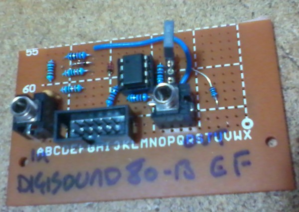
| Perfed up the Digisound 80-13 envelope follower, and it works pretty well. There is some lag on the attack, but I can live with that, I guess. Just need to redesign the second engine PCB, now, and then work up a panel for this. |
|
|
Back to top
|
|
|
Ayab
Joined: Oct 27, 2015
Posts: 186
Location: London, UK
|
| Posted: Sun Sep 20, 2020 11:30 pm Post subject:
|
|
|
Looks like you have put lots of hard work into this. Good work.
A description of how it sounds/how you have tweaked it compared to the Serge EQ you built would be interesting - and how you would use the extra outs.
Please let me know when it is done and you have finished the panel - if you sell pcbs/panels |
|
|
Back to top
|
|
|
AlanP
Joined: Mar 11, 2014
Posts: 746
Location: New Zealand
Audio files: 41
|
| Posted: Wed Sep 30, 2020 3:29 pm Post subject:
|
|
|

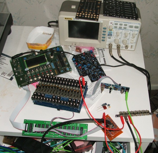
This is the VCA/Summing board, after patching. Two opamps (long wires) had their inputs reversed, needing traces cut and patched, and the 2164's are currently bypassing the individual output opamps and are summed directly by the final opamp. I only included two because one, I only had two when testing, and two, I don't need all sixteen bands to be VCA'ed to test how a handful work together. I've got a new revision that incorporates all this
To the right of that is the jack/slider PCB. Two slider LEDs had no ground connection, hence the two 'U' patch wires. I only had 50kB linear taper sliders on hand, and all the resistors are to change them to a 10kA audio taper. I've got a new revision with the added grounds, and also optional SMD resistor placements to adjust the slider taper/resistance (see the link below for more on this.)
https://www.diystompboxes.com/analogalchemy/emh/emh.html -- click 'Tapered Pot'.

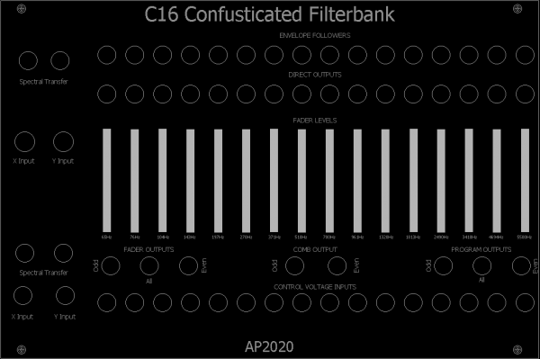
For fun, this is a mockup of what the user should see in the end (with, obviously, a panel on top when done!)
Input -- the two toggle switches on top control whether the envelopes of odd control the VCAs of even (an 8 channel vocoder, if you have separate odd/even inputs patched), the top two Input jacks are gates in to control this as well. The bottom two jacks are Odd/Even inputs (normalled to each other), with attenuators above them.
As a side note -- photographing shiny things is a bit of a pig! |
|
|
Back to top
|
|
|
blue hell
Site Admin

Joined: Apr 03, 2004
Posts: 24451
Location: The Netherlands, Enschede
Audio files: 297
G2 patch files: 320
|
| Posted: Wed Sep 30, 2020 3:41 pm Post subject:
|
|
|
| AlanP wrote: | | As a side note -- photographing shiny things is a bit of a pig! |
Oh you're not doing bad, quite nice shots. Aaand .. also ... you can diffuse the light source when using the cam's flash by using a small (makeup) mirror to direct the flash to the ceiling .. might help
Looks like you'll have a very nice module in a while!
_________________
Jan
also .. could someone please turn down the thermostat a bit.
 |
|
|
Back to top
|
|
|
AlanP
Joined: Mar 11, 2014
Posts: 746
Location: New Zealand
Audio files: 41
|
|
|
Back to top
|
|
|
AlanP
Joined: Mar 11, 2014
Posts: 746
Location: New Zealand
Audio files: 41
|
|
|
Back to top
|
|
|
AlanP
Joined: Mar 11, 2014
Posts: 746
Location: New Zealand
Audio files: 41
|
|
|
Back to top
|
|
|
AlanP
Joined: Mar 11, 2014
Posts: 746
Location: New Zealand
Audio files: 41
|
| Posted: Sun Nov 01, 2020 6:31 pm Post subject:
|
|
|

The new revision PCBs arrived, including the panel for this. Usefully, the old revision panel-PCBs (with the jacks, and controls and stuff) all work with the new revision engine PCBs, so I don't need to desolder sixteen sliders!
I still have to populate the two new engine PCBs. Boy, is that going to be fun...
(Oh, and putting the 56 odd jack nuts on was about as much fun as you think it would be.) |
|
|
Back to top
|
|
|
AlanP
Joined: Mar 11, 2014
Posts: 746
Location: New Zealand
Audio files: 41
|
|
|
Back to top
|
|
|
AlanP
Joined: Mar 11, 2014
Posts: 746
Location: New Zealand
Audio files: 41
|
| Posted: Thu Dec 03, 2020 9:33 pm Post subject:
|
|
|
Ooof. Work has gone busy, really busy. This week, overtime monday through friday, and eight hours on Saturday tomorrow. On the one hand, money for parts isn't an issue. On the other hand, time to solder said parts is an issue.
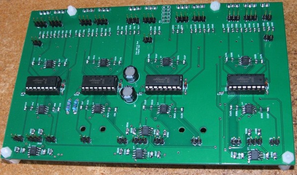
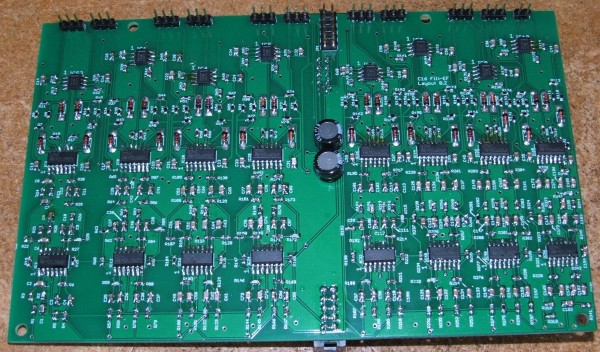
I've soldered up EngB, the board with the filters themselves and the new envelope followers. If I ever do another take on this project, the filters are getting their own, dedicated PCB so I can just solder them up once and then do new revisions of the other submodules.
The good news is that the followers work nicely. I plugged in a VCO to the Input, and as I messed with the frequency of the VCO, I could see the lights on the panel travel up and down the spectrum (as opposed to the old followers, which lit up whenever the heck they felt like it.) One or two LEDs aren't lighting up, so I need to test whether it's the filter for that channel (everything follows on from the filters), or whether it's the follower. I'm going to do that when I have the energy... stupid overtime.
Once all of this board is verified good, I'm then going to go through the gain stages -- the gain on the input buffer (currently set to 3x gain... too high, I'm pretty sure it's blowing out the VCAs), and the gain on the various output mixers (faders, VCAs, comb) so that they all come out at roughly the same p-p levels. Should I set the fader out levels so that when the faders are at max, the gain is x1 (compared to the input), or so that they have a bit more gain if you dime all the faders?
I also need to test the spectral transfer switches, and see if the resistors are passing the right amount of signal (or if they're going to distort those VCAs... again...)
Making progress, slowly, but then I've wanted this module for years. I can wait a bit. It's probaby vanity, but I also think these circuit boards are looking dead spiffy!
| Description: |
|
| Filesize: |
720.48 KB |
| Viewed: |
192 Time(s) |
| This image has been reduced to fit the page. Click on it to enlarge. |
|
|
|
|
Back to top
|
|
|
AlanP
Joined: Mar 11, 2014
Posts: 746
Location: New Zealand
Audio files: 41
|
| Posted: Tue Dec 29, 2020 10:22 pm Post subject:
|
|
|
The bad news is that I did something really stupid that I don't understand with the spectral transfer system. It uses a bunch of Jfets (MMBFJ201) to connect the envelope follower out of one channel, to the VCA CV In of the paired channel. At the moment, like an idiot, I have the gate either at +12V (through a 100k resistor), or at ground (though same 100k resistor.) Because I'm an idiot, I didn't do my basic research on this.
The good news is that hopefully, it's just going to need a new revision of the Input PCB, the nice, simple PCB that is just one 30x100mm pcb with no extra guff.
The annoying news is that I think I may end up having to... *shudder*... breadboard something. |
|
|
Back to top
|
|
|
AlanP
Joined: Mar 11, 2014
Posts: 746
Location: New Zealand
Audio files: 41
|
| Posted: Fri Apr 28, 2023 8:55 am Post subject:
|
|
|
I've come back to it... I thought I had linear VCA submodules. They're exponential. Another PCB revision is underway  |
|
|
Back to top
|
|
|
AlanP
Joined: Mar 11, 2014
Posts: 746
Location: New Zealand
Audio files: 41
|
| Posted: Fri May 19, 2023 1:54 pm Post subject:
|
|
|
Yes, it was the VCAs, which were exponential. They are now linear, and it turns out the spectral transfer stuff was working just fine.


 |
|
|
Back to top
|
|
|
PHOBoS
Joined: Jan 14, 2010
Posts: 5845
Location: Moon Base
Audio files: 709
|
|
|
Back to top
|
|
|
blue hell
Site Admin
Joined: Apr 03, 2004
Posts: 24451
Location: The Netherlands, Enschede
Audio files: 297
G2 patch files: 320
|
| Posted: Fri May 19, 2023 4:36 pm Post subject:
|
|
|
fom that I guess
| pho wrote: | | so, is it fully working now ? |
that it finally is 
Must be a nice module too!
_________________
Jan
also .. could someone please turn down the thermostat a bit.
|
|
|
Back to top
|
|
|
AlanP
Joined: Mar 11, 2014
Posts: 746
Location: New Zealand
Audio files: 41
|
| Posted: Fri May 19, 2023 7:36 pm Post subject:
|
|
|
| Yep, finally sorted. I'm pretty sure. Now I just need to make rack space for this monster |
|
|
Back to top
|
|
|
|

 Forum index » DIY Hardware and Software