| Author |
Message |
NuttyMonk
Joined: Jun 30, 2020
Posts: 63
Location: UK
|
 Posted: Fri Apr 30, 2021 1:12 pm Post subject:
Resettable Clock for synchronisation Posted: Fri Apr 30, 2021 1:12 pm Post subject:
Resettable Clock for synchronisation |
  |
|
Hi all,
i am trying to figure out a way to create a clock signal which can be controlled using potentiometers and external voltages and can also be reset asynchronously so that i can keep multiple clocks in time with each other using a trigger at the start of each bar.
I've looked at 555 Timer IC's and have managed all of that except the reset part. Does anyone have an idea for how to go about this? Either with 555 Timers or some other method?
My brain is about to explode trying to understand the 555 timer and i'm getting really frustrated.
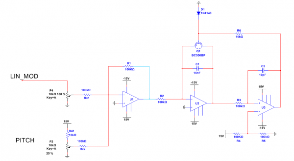
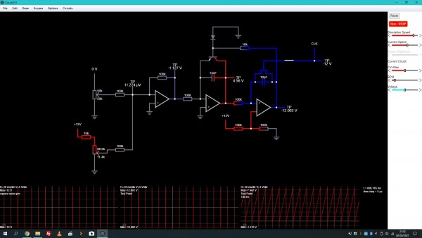
I've added an image and Falstad File of my current 555 Timer setup which works well, except for resetting.
Cheers
NM
p.s. i guess i need an oscillator which can be adjusted by pots, control voltages and has a sync function like hard sync and is linear not exponential
| Description: |
|
| Filesize: |
195.56 KB |
| Viewed: |
164 Time(s) |
| This image has been reduced to fit the page. Click on it to enlarge. |
|
| Description: |
|

Download (listen) |
| Filename: |
555 Falstad Sim.txt |
| Filesize: |
3.09 KB |
| Downloaded: |
136 Time(s) |
|
|
|
Back to top
|
|
 |
gabbagabi

Joined: Nov 29, 2008
Posts: 652
Location: Berlin by n8
Audio files: 23
|
| Posted: Sun May 02, 2021 11:59 am Post subject:
|
|
|
hm,
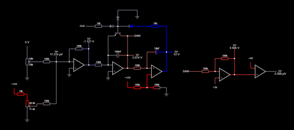
i guess i would go for linear saw vco´s
they usually sync better
and you have better pwm options if you would like to have different gate lengths
i remember 555 can cause problems cos of heavie current use when switching |
|
|
Back to top
|
|
|
NuttyMonk
Joined: Jun 30, 2020
Posts: 63
Location: UK
|
| Posted: Sun May 02, 2021 12:13 pm Post subject:
|
|
|
Thanks gabbagabi,
you know of any designs? i can find plenty of saw vco designs but they all employ exponential converters. I'm not good enough at this stuff yet to be able to change one of those designs to linear.
Cheers
NM |
|
|
Back to top
|
|
|
gabbagabi
Joined: Nov 29, 2008
Posts: 652
Location: Berlin by n8
Audio files: 23
|
|
|
Back to top
|
|
|
NuttyMonk
Joined: Jun 30, 2020
Posts: 63
Location: UK
|
| Posted: Sun May 02, 2021 12:44 pm Post subject:
|
|
|
Nice. Thanks Gabbagabi.
I'll try simulating it and breadboarding it later tonight.
Cheers
NM |
|
|
Back to top
|
|
|
NuttyMonk
Joined: Jun 30, 2020
Posts: 63
Location: UK
|
| Posted: Sun May 02, 2021 1:57 pm Post subject:
|
|
|
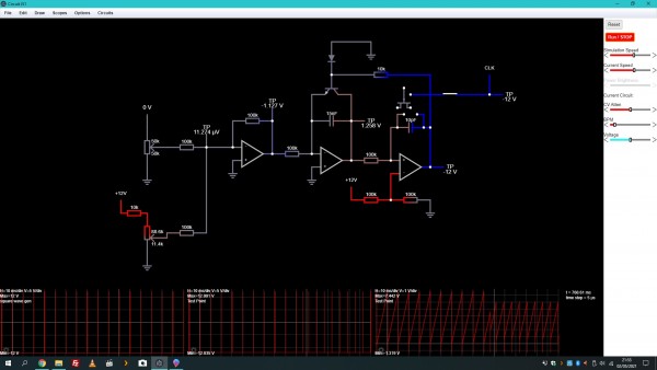
I've simulated it and it works well. The only problem i'm having is implementing a reset function. I'm shorting the 10pf cap using a JFET but that stops the regular pulses coming from U3 from working properly.
The pulses are -12V to 12V on the JFETs base(???) leg. Not sure what that leg is called on a JFET.
Any ideas?
Cheers
NM
| Description: |
|
| Filesize: |
187.79 KB |
| Viewed: |
131 Time(s) |
| This image has been reduced to fit the page. Click on it to enlarge. |
|
| Description: |
|
| Filesize: |
190.84 KB |
| Viewed: |
150 Time(s) |
| This image has been reduced to fit the page. Click on it to enlarge. |
|
|
|
|
Back to top
|
|
|
blue hell
Site Admin

Joined: Apr 03, 2004
Posts: 24409
Location: The Netherlands, Enschede
Audio files: 297
G2 patch files: 320
|
| Posted: Sun May 02, 2021 4:45 pm Post subject:
|
|
|
How I see things ...
For a reset you should short C1, and as as Q1 already does that peridically for the 'regular' reset .. it should be sufficient to make the base of Q1 forced high for a short! time.
This should 'override' the regular reset from U3, so maybe a (left pointing) diode in series with R6 and then an extra diode and resistor where you put in the (short) reset pulse?
The pulse must be short, as oscillation will be inhibited for the duration of the reset signal. But it must not be too short, as otherwise the capacitor will not be discharged completely. You may want some differentiating RC thingy to make a short pulse with a defined length there, and then fiddle a bit with the RC time.
The 'base' of a FET is called the gate.
C2 (the 10pF one) is just making the regular reset from U3 a bit faster.
_________________
Jan
also .. could someone please turn down the thermostat a bit.
 |
|
|
Back to top
|
|
|
NuttyMonk
Joined: Jun 30, 2020
Posts: 63
Location: UK
|
|
|
Back to top
|
|
|
blue hell
Site Admin
Joined: Apr 03, 2004
Posts: 24409
Location: The Netherlands, Enschede
Audio files: 297
G2 patch files: 320
|
| Posted: Sun May 02, 2021 8:12 pm Post subject:
|
|
|
| NuttyMonk wrote: | | It's gonna be a long time before i'm even slightly competent with this stuff. |
You go pretty fast tho, with just a couple of words that could have been confusing. which I was afraid of ...
Good to see you have some progress, may the breadboarding work too :)
And yes, clock to trigger does that shortening.
_________________
Jan
also .. could someone please turn down the thermostat a bit.
|
|
|
Back to top
|
|
|
gabbagabi
Joined: Nov 29, 2008
Posts: 652
Location: Berlin by n8
Audio files: 23
|
| Posted: Mon May 03, 2021 12:47 pm Post subject:
|
|
|
uh, ah
things are going fast these days 
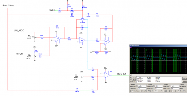
i dunno if the idea wiht all the diodes on the transistor base will work, but i like how it looks, and my simulator also says it works.
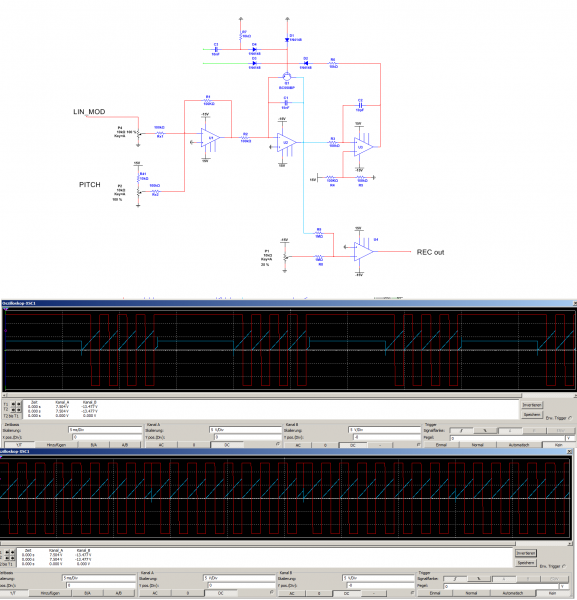
i included an idea for the start/stop input, and seperate reset input, the simulator says again it works 
do you can breadboard? iam exepted from any hardware otherwise i would do it myself
a guessing:
100nf as integration cap could be a bit high in reality, because it could be that the reset time (determinated by the 10pF cap) could be to short to discharge a fully loaded 100nf Cap, i have in memory that if putted a 15nF in.
same time i was using a 10Mohm resistor as integration resistor (R2), i guess that way i was reaching like 3 seconds or so.
are you planing to have the pulse width modulated?
cheers, looking forward to hear about your progress
| Description: |
|
| Filesize: |
143.08 KB |
| Viewed: |
137 Time(s) |
| This image has been reduced to fit the page. Click on it to enlarge. |
|
|
|
|
Back to top
|
|
|
NuttyMonk
Joined: Jun 30, 2020
Posts: 63
Location: UK
|
| Posted: Mon May 03, 2021 1:59 pm Post subject:
|
|
|
Thanks Gabbagabi.
The Start/Stop works well. The rest i'm not sure about.
This is going to be for a clock and the counter chip i am using (CD4029) counts each time it gets a rising transition so i might not need the pulse output. I have inverted the saw wave so i get a hard rising transition whenever the capacitor is shorted. This works well to generate a pulse output using a comparator but when the reset pulse is activated the saw wave might not have dropped below the comparators limit so no new pulse is created. Although it looks like it works ok in your simulation.
The saw wave on it's own gives me a hard rising transition anyway which is all i need.
The other problem is getting it to work well down in the LFO range as a clock, so down in the range below 8Hz is probably what i need. Not sure how to do that if the capacitor can't be too big.
I'll keep fiddling with it and see if i can get it to work using your setup.
Cheers
NM |
|
|
Back to top
|
|
|
NuttyMonk
Joined: Jun 30, 2020
Posts: 63
Location: UK
|
| Posted: Thu May 06, 2021 12:04 pm Post subject:
|
|
|
I went looking around to see what other people have been using for their clocks and i came across Fonitroniks VC clock. It's exponential, not linear, but that's ok i think.
http://www.modular.fonik.de/pdf/VCClockSCH.pdf
The way it works is easy for me to understand and i think it should be easy to add in an On/Off switch and a reset input.
By shorting Pin 5 on IC1B to ground, the cycle resets by shorting C10. Works well in my simulation. Easy to implement an On/Off switch. Not sure about how to go about the Reset/Sync part of it though. I'm not good with transistors yet although that would be the obvious choice. I'm thinking about just using a single SPST switch IC instead. I can understand that easily enough.
Cheers
NM
p.s. there is already a forum post about syncing Fonitroniks clock here on EM
https://electro-music.com/forum/viewtopic.php?highlight=clock&t=47164 |
|
|
Back to top
|
|
|
gabbagabi
Joined: Nov 29, 2008
Posts: 652
Location: Berlin by n8
Audio files: 23
|
|
|
Back to top
|
|
|
|

 Forum index » DIY Hardware and Software