| Author |
Message |
robynm
Joined: May 30, 2013
Posts: 10
Location: London
|
 Posted: Fri Jun 07, 2013 4:16 am Post subject:
Integrator / Schmitt VCO Posted: Fri Jun 07, 2013 4:16 am Post subject:
Integrator / Schmitt VCO
Subject description: Designing a VCO |
  |
|
Hi everyone, congratulations on this beautiful forum. This is my first post here, but I have been acquiring a lot of knowledge by just reading other people's threads so far.
Now I want to design my own VCO. I think my understanding of electronics is getting good enough to do it... with help of course  My design won't be perfect but I don't mind a bit of glitch and building from the ground up will surely teach me a lot. My design won't be perfect but I don't mind a bit of glitch and building from the ground up will surely teach me a lot.
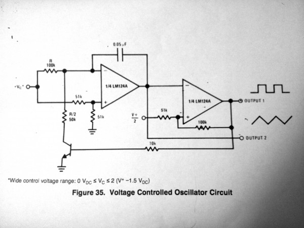
So the starting point of my VCO is an integrator / schmitt trigger. I found it on the datasheet of Texas Instruments for the LM124 (p.17) and I recently came across it in the book The Art Of Electronics. It also seems to be the heart of Thomas Henry's VCO-1. I want to make sure I really understand what's going on in those schematics before I start adding to it.
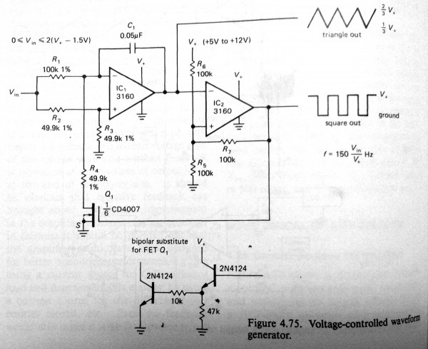
Attached are both the TI and the AOEE schematics. Two things strike me:
1. The 49.9K resistors in the AOEE book are replaced by 51K resistors in the TI datasheet. Why is this? Which option is... better?
2. In the TI schematics there is a BJT with a 10K at the base to "relax" the inverting input of the integrator and allow the cap to discharge. In the AOEE they use a FET with no resistor at the gate and provide a more complex circuit made of two transistors if you decide to use a BJT.
3a. I have built the TI version and I know it works. But I understand that the FET seems to be a better option as it is voltage driven and the op-amp will output mostly voltage and almost no current. Is this right? Why does the TI version even work?
3b. In the AOEE alternative BJT version they use two transistors. Are the basically just amplifying the signal?
Thanks in advance!
| Description: |
| from The Art of Electronics (p. 240) |
|
| Filesize: |
882.06 KB |
| Viewed: |
615 Time(s) |
| This image has been reduced to fit the page. Click on it to enlarge. |
|
| Description: |
|
| Filesize: |
1.86 MB |
| Viewed: |
488 Time(s) |
| This image has been reduced to fit the page. Click on it to enlarge. |
|
|
|
|
Back to top
|
|
 |
elektrouwe
Joined: May 27, 2012
Posts: 149
Location: Germany
|
Posted: Sun Jun 09, 2013 5:27 am Post subject:
Re: Integrator / Schmitt VCO
Subject description: Designing a VCO |
|
|
| robynm wrote: |
1. The 49.9K resistors in the AOEE book are replaced by 51K resistors in the TI datasheet. Why is this? Which option is... better?
|
R4( references from AOE book) must be exactly 1/2 of R1 to get a symmetrical triangle. I always use 2 pcs.R1 in parallel for R4, or 2 pcs. R4 in series for R1, because then you can choose any standard R value (47k...220k). The same value can be used for R2 and R3 and also for R5,6,7 - then it's simply 1 value for all Rs to get the best precision.
| robynm wrote: |
2. In the TI schematics there is a BJT with a 10K at the base to "relax" the inverting input of the integrator and allow the cap to discharge. In the AOEE they use a FET with no resistor at the gate and provide a more complex circuit made of two transistors if you decide to use a BJT.
|
for small currents like here , the CE saturation voltage is only some ten mV, which does not do much concerning symmetry. The circuit can be improved by swapping C and E of the discharge trans. and tweaking the 10k base resistor until you get <2mV Vce-sat. I don't see a reason to use a a second transistor to buffer the comparator because the 3160 can easily drive >1.5 mA, which is required here. A discrete MOSFET can be used instead of the 4007 or a 4066/4053/.... analog switch if you prefer ICs.
The circuit would even work with a diode as discharge switch ( symmetry/linearity not so nice then ...) or use a true comparator with OC like LM339 to get rid of the extra discharge switch. |
|
|
Back to top
|
|
|
robynm
Joined: May 30, 2013
Posts: 10
Location: London
|
Posted: Tue Jun 11, 2013 11:00 pm Post subject:
Re: Integrator / Schmitt VCO
Subject description: Designing a VCO |
|
|
Thanks for your answer.
| elektrouwe wrote: |
R4( references from AOE book) must be exactly 1/2 of R1 to get a symmetrical triangle. I always use 2 pcs.R1 in parallel for R4, or 2 pcs. R4 in series for R1, because then you can choose any standard R value (47k...220k). The same value can be used for R2 and R3 and also for R5,6,7 - then it's simply 1 value for all Rs to get the best precision. |
Get it.
| elektrouwe wrote: |
for small currents like here , the CE saturation voltage is only some ten mV, which does not do much concerning symmetry. The circuit can be improved by swapping C and E of the discharge trans. and tweaking the 10k base resistor until you get <2mV Vce-sat. I don't see a reason to use a a second transistor to buffer the comparator because the 3160 can easily drive >1.5 mA, which is required here. A discrete MOSFET can be used instead of the 4007 or a 4066/4053/.... analog switch if you prefer ICs.
The circuit would even work with a diode as discharge switch ( symmetry/linearity not so nice then ...) or use a true comparator with OC like LM339 to get rid of the extra discharge switch. |
This is still pretty obscure for me.
1. I did a simulation of the circuit with C and E swapped and the triangle's amplitude increases. Why is that? I thought that C always had to be the positive side and E the negative.
2. Also, in the Art of Electronics, there is no resistor between the 1/2 V+ and the non inverting input of the schmitt trigger. If I don't put this resistor in my simulation I get a very fast / unstable oscillation. If I put it the oscillation works but at only half the frequency indicated on the schematics (f= 150 x (Vin / V+)).
3. I am trying to learn circuit analysis because there is no way around it. Kirchoff is still causing me trouble but I'll get there. Is it out of reach for me to understand how they come up with this equation to calculate the frequency?
Edit: Link to the simulation:
Simulation
_________________
I make music
Last edited by robynm on Fri Oct 18, 2013 2:01 am; edited 1 time in total |
|
|
Back to top
|
|
|
elektrouwe
Joined: May 27, 2012
Posts: 149
Location: Germany
|
Posted: Wed Jun 12, 2013 7:24 am Post subject:
Re: Integrator / Schmitt VCO
Subject description: Designing a VCO |
|
|
| robynm wrote: |
1. I did a simulation of the circuit with C and E swapped and the triangle's amplitude increases. Why is that? I thought that C always had to be the positive side and E the negative.
|
this should not be and I didn't see it when swapping C and E in your linked example !?? In fact you will see nothing in these tiny simulation windows, because we talk about some mV difference in a some-volts signal.
You can swap C and E with any transistor and it will still work with the disatvantage of a very low (reverse-) gain and the advantage of a very low saturation voltage.
| robynm wrote: |
2. Also, in the Art of Electronics, there is no resistor between the 1/2 V+ and the non inverting input of the schmitt trigger. ..
|
there is one : it is R5 parallel R6 . When you replace the voltage divider R5,R6 connected to V+ by R5 parallel R6 connected to V+/2 you will have an equivalent circuit with the same internal resistance.
| robynm wrote: |
3. I am trying to learn circuit analysis because there is no way around it. Kirchoff is still causing me trouble but I'll get there. Is it out of reach for me to understand how they come up with this equation to calculate the frequency?
|
don't worry:
1. calculate the upper and lower switching thresholds of the comparator:
if comp. Vout is v+ then R7 is parallel to R6 and the voltage over R5 is 2/3 V+
if comp. Vout is 0V, then R7 is parallel to R5 and the voltage over them is 1/3 v+
2. calculate the output voltage range of the integrator :
amplitude of the triangle is upper minus lower threshold = 2/3V+ - 1/3V+ = V+/3
3. calculate the current that fills C1 :
let comp. Vout = 0 => Q1 is OFF => integrator is ramping down
constant current flowing into C1 == current flowing through R1
noninverting input is held @ Vin/2 so opamp keeps inverting output also @ Vin/2
Ic1 = Ir1 = Vr1/R1 = ( Vin - Vin/2)/R1 = (Vin/2)/R1
4. calculate output voltage ramp (absolute value, sign changes for up/down ramp) of the integrator:
down from 2/3V+ to 1/3V+. Lets calculate the time for this ramp:
voltage change in a capacitor is high when the charging time is high, the charging current is
high and the capacitor is small. here:
deltaV = (Ir1 * Tramp) / C1
because deltaV is the ramp amplitude and Ir1 = (Vin/2)/R1 we can write :
deltaV = V+/3 = (Vin/2)/R1 * T / C1
5. calculate the ramp time T :
T = ( 2 * V+ * C1 * R1) / ( 3 * Vin )
because 1 periode is 2 ramps (up&down) frequency can be calculated as:
f = 1/(2T) = 3 * Vin / ( 2*2 * R1 * C1 * V+)
with R1 = 0.1e6 and C1 = 50e-9 you end up with the formula in the schematics:
f = 150 * Vin / V+ |
|
|
Back to top
|
|
|
robynm
Joined: May 30, 2013
Posts: 10
Location: London
|
| Posted: Wed Oct 16, 2013 10:37 pm Post subject:
|
|
|
Electrouwe I am sorry I never thanked you for your advice. I breadboarded the VCO, it didn't work, I got upset and decided to start learning drums...
I have recently printed out your answer though and carefully read it while inspecting the circuit and things make more sense now.
This VCO is back on my to-do list so I'll probably revive this thread pretty soon.
Thank you again, sorry it took so long for me to say it 
_________________
I make music |
|
|
Back to top
|
|
|
elektrouwe
Joined: May 27, 2012
Posts: 149
Location: Germany
|
| Posted: Thu Oct 17, 2013 2:16 am Post subject:
|
|
|
| You're welcome and good luck with your next try |
|
|
Back to top
|
|
|
robynm
Joined: May 30, 2013
Posts: 10
Location: London
|
| Posted: Fri Dec 06, 2013 12:35 am Post subject:
|
|
|
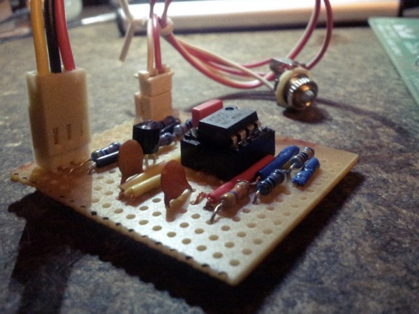
OK So I have finally finished the core of this VCO and soldered it to stripboard. It works a charm and I am really happy. I've even breadboarded a Baby 8 sequencer to make it sing. I felt like a dad hearing his kid say his first word
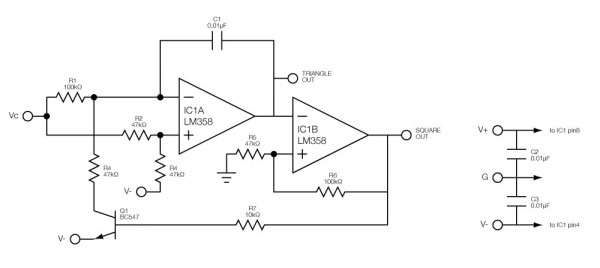
Now I would like to give this thing a bit of range because so far I can only go from about 333Hz to 666Hz corresponding to a 12V range in the control voltage.
From what I've gathered looking at other VCOs and reading numerous articles, what I need is to convert this voltage into current with a transconductance device. That would allow me to control the amount of current that charges C1 and get the maximum range?
I want to keep things dead simple and avoid using an OTA for the moment because I want to learn how things work (otherwise I would just build Thomas Heny's VCO-1 right away).
It seems that FETs are voltage driven and control a current. Can I just implement some sort of FET amplifier at the input of my existing VCO?
| Description: |
|
| Filesize: |
33.87 KB |
| Viewed: |
440 Time(s) |
| This image has been reduced to fit the page. Click on it to enlarge. |
|
| Description: |
|
| Filesize: |
252.58 KB |
| Viewed: |
316 Time(s) |
| This image has been reduced to fit the page. Click on it to enlarge. |
|
_________________
I make music |
|
|
Back to top
|
|
|
robynm
Joined: May 30, 2013
Posts: 10
Location: London
|
| Posted: Tue Dec 10, 2013 2:36 am Post subject:
|
|
|
Bump please!
_________________
I make music |
|
|
Back to top
|
|
|
gerry
Joined: Jul 18, 2021
Posts: 2
Location: mexico
|
Posted: Sun Jul 18, 2021 12:16 am Post subject:
Re: Integrator / Schmitt VCO
Subject description: Designing a VCO |
|
|
| Quote: |
1. calculate the upper and lower switching thresholds of the comparator:
if comp. Vout is v+ then R7 is parallel to R6 and the voltage over R5 is 2/3 V+
if comp. Vout is 0V, then R7 is parallel to R5 and the voltage over them is 1/3 v+
2. calculate the output voltage range of the integrator :
amplitude of the triangle is upper minus lower threshold = 2/3V+ - 1/3V+ = V+/3
3. calculate the current that fills C1 :
let comp. Vout = 0 => Q1 is OFF => integrator is ramping down
constant current flowing into C1 == current flowing through R1
noninverting input is held @ Vin/2 so opamp keeps inverting output also @ Vin/2
Ic1 = Ir1 = Vr1/R1 = ( Vin - Vin/2)/R1 = (Vin/2)/R1
4. calculate output voltage ramp (absolute value, sign changes for up/down ramp) of the integrator:
down from 2/3V+ to 1/3V+. Lets calculate the time for this ramp:
voltage change in a capacitor is high when the charging time is high, the charging current is
high and the capacitor is small. here:
deltaV = (Ir1 * Tramp) / C1
because deltaV is the ramp amplitude and Ir1 = (Vin/2)/R1 we can write :
deltaV = V+/3 = (Vin/2)/R1 * T / C1
5. calculate the ramp time T :
T = ( 2 * V+ * C1 * R1) / ( 3 * Vin )
because 1 periode is 2 ramps (up&down) frequency can be calculated as:
f = 1/(2T) = 3 * Vin / ( 2*2 * R1 * C1 * V+)
with R1 = 0.1e6 and C1 = 50e-9 you end up with the formula in the schematics:
f = 150 * Vin / V+ |
hi , can you help to understand all this math???
how you get that 150 ?? cos R1 is 100k & C1 is 50nf ?? so just put together?? 150...so how i can change "150" for a biger number? or how i can change this value with knowledge? i would like to speed up this osc. maybe 20khz.....[/quote] |
|
|
Back to top
|
|
|
Steveg

Joined: Apr 23, 2015
Posts: 184
Location: Perth, Australia
|
| Posted: Sun Jul 18, 2021 6:57 pm Post subject:
|
|
|
I'm not sure that last line is correct but we'll see.
f = 3 * Vin / ( 2 * 2 * R1 * C1 * V+ )
Just in case yo don't have a programming background '*' is the symbol for multiplication in most programming languages.
Lets substitute in the component values ...
f = 3 * Vin / ( 4 * 100000 * 0.00000005 * V+ )
Multiply out some more ...
f = 3 * Vin / ( .02 * V+ )
Separate out the control voltage effect ...
f = ( 3 / 0.02 ) * ( Vin / V+ )
f = 150 * ( Vin / V+ )
So, perfectly correct. ( Vin / V+ ) means the ratio of your control voltage over your supply voltage. The lower your control voltage the lower the frequency.
So if we want a 20kHz maximum frequency ( and setting aside the control voltage effects )
f = 3 / ( 4 * R1 * C1 )
Substituting in the values we want ...
20000 = 3 / ( 4 * R1 * C1 )
Multiply both sides by ( R1 * C1 )
20000 * ( R1 * C1 ) = 3 / 4
Divide both sides by 20000
R1 * C1 = 3 / 80000
R1 * C1 = 0.0000375
R1 is measured in ohms and C1 is measured in farads but remember most component values include some form of scaling so a 100k resistor is 100 x 1000 ohms and a 50nF capacitor is 50 x .000000001 Farads.
You want a frequency a bit over 100 times higher so we'll set R1 at 10K ... and substitute that in
10000 * C1 = 0.0000375
C1 = 0.0000375 / 10000
C1 = 0.00000000375 Farads
Lets convert that to nF
C1 = 3.75 nF
Now remember that is for (Vin / V+) equal to 1 - you control voltage is the same as your supply voltage.
That would give you a range from whatever the minimum frequency is up to the audible limit but your control is gong to be awful. You are unlikely to be precisely able to get any particular frequency because you wont be able to generate accurate enough voltages. Note that the original circuit didn't go all the way to 0 Hz. I'm guessing that you are only going to get a tunable range from 10KHz to 20KHz. |
|
|
Back to top
|
|
|
gerry
Joined: Jul 18, 2021
Posts: 2
Location: mexico
|
| Posted: Mon Jul 19, 2021 12:21 am Post subject:
|
|
|
| Steveg wrote: | I'm not sure that last line is correct but we'll see.
f = 3 * Vin / ( 2 * 2 * R1 * C1 * V+ )
Just in case yo don't have a programming background '*' is the symbol for multiplication in most programming languages.
Lets substitute in the component values ...
f = 3 * Vin / ( 4 * 100000 * 0.00000005 * V+ )
Multiply out some more ...
f = 3 * Vin / ( .02 * V+ )
Separate out the control voltage effect ...
f = ( 3 / 0.02 ) * ( Vin / V+ )
f = 150 * ( Vin / V+ )
So, perfectly correct. ( Vin / V+ ) means the ratio of your control voltage over your supply voltage. The lower your control voltage the lower the frequency.
So if we want a 20kHz maximum frequency ( and setting aside the control voltage effects )
f = 3 / ( 4 * R1 * C1 )
Substituting in the values we want ...
20000 = 3 / ( 4 * R1 * C1 )
Multiply both sides by ( R1 * C1 )
20000 * ( R1 * C1 ) = 3 / 4
Divide both sides by 20000
R1 * C1 = 3 / 80000
R1 * C1 = 0.0000375
R1 is measured in ohms and C1 is measured in farads but remember most component values include some form of scaling so a 100k resistor is 100 x 1000 ohms and a 50nF capacitor is 50 x .000000001 Farads.
You want a frequency a bit over 100 times higher so we'll set R1 at 10K ... and substitute that in
10000 * C1 = 0.0000375
C1 = 0.0000375 / 10000
C1 = 0.00000000375 Farads
Lets convert that to nF
C1 = 3.75 nF
Now remember that is for (Vin / V+) equal to 1 - you control voltage is the same as your supply voltage.
That would give you a range from whatever the minimum frequency is up to the audible limit but your control is gong to be awful. You are unlikely to be precisely able to get any particular frequency because you wont be able to generate accurate enough voltages. Note that the original circuit didn't go all the way to 0 Hz. I'm guessing that you are only going to get a tunable range from 10KHz to 20KHz. |
beautiful just beatiful...tnks for your explanation now i get it...
so if i follow the rule where i take in consideration vin/v+ everything would work ok?... cos if a take the first circuit and just change the 50nf to 1nf..yes the freq..goes up BUT the triangle wave dont follow the threshold of the smith tigger/comparator any more so the amplitud with more freq... increase alot..i mean if threshold is i.e. +-2v the triangle wave form has to be 4vpp all way, but that not happen if i change only the cap to lower value... the waveform increase a lot in amplitud
so with this rule math taking vin/v+ in consideration the triangle wave will follow the threshold???
tnks again  |
|
|
Back to top
|
|
|
Steveg
Joined: Apr 23, 2015
Posts: 184
Location: Perth, Australia
|
| Posted: Mon Jul 19, 2021 1:20 am Post subject:
|
|
|
| Sorry, can't answer that. I know digital logic and I can do maths but I'm not a guru on analog circuits. I would not have thought there could be a problem with the comparator, it should be good up to the MHz range. Maybe there is some interaction in the circuit I'm not seeing. |
|
|
Back to top
|
|
|
|

 Forum index » DIY Hardware and Software
