| Author |
Message |
Ruebezahl

Joined: Mar 09, 2014
Posts: 112
Location: Taiwan
Audio files: 4
|
 Posted: Wed May 19, 2021 2:12 am Post subject:
Logical Steps - patchable CMOS logic sequencer Posted: Wed May 19, 2021 2:12 am Post subject:
Logical Steps - patchable CMOS logic sequencer
Subject description: A sequencer based on 4051, 4040, 4093 CMOS technology |
  |
|
The idea is based on some instructions in the genius “Logic Noise Series” on hackaday, written by Elliot Williams, which i can wholeheartedly recommend. In particular this article: “The switching Sequencer has the beat”
https://hackaday.com/2015/02/23/logic-noise-the-switching-sequencer/
Although i had a first breadboarded version done almost immediately, the whole process until everything was boxed and free of errors took me quite long, since i used some new techniques and learned a new program from scratch, called Inkscape (an open source vector graphic program), to design the layout.
So a bit more details about this machine, both inside and outside: <Logical> is an 8 step sequencer that can be controlled through patching and the behaviour can range from straight 1-2-3-4 to really funky polyrythms, all the way to really chaotic chaos. At the core is the idea of this article by Elliot Williams, that is based on several CMOS logic chips. At the heart is a 4051 8 channel (de-) mutliplexer that is controlling the feedback in an oscillator run on a 4093 NAND-Gate, thus working as a kind of non-linear sequencer. The remaining three Nand Gates are used to set up three independent oscillators, which can be directly listened to or used to control the three logic inputs A, B, C of the 4051, that determine which of the 8 potentiometers is controlling the main oscillator at each time. For a much better description of this concept please refer to the article by Elliot WIlliams i linked up there. For further variation and less chaotic control of the sequencer there is a 4040 Divider, plus an AND and an OR gate, as well as two envelope generators, also based on an idea by Elliot Williams. The whole machine is patchable through those connectors (i actually don’t know how they are called) that are ring and fork shaped and come in different colors, and alligator clips. A ring shaped connector is an input, a fork shaped connector is an output. There is also a mixing section with two tracks and a built in filter, based on a 4069UBE. The layout of the box is based on the case of a DVD package for learning Indonesian. It’s a very sturdy but light box, and the cool thing is that the inlet can be taken out and be replaced with whatever design you print on a paper, and it is protected by the outer foil.
Video: https://www.youtube.com/watch?v=bn-p-8l22es


Problems i came across:
- To my surprise, the dvd case was almost completely out of thick cardboard, which was almost impossible to drill, so i ended up with some really ugly holes and had to buy some special tools to hammer the holes into the case.
-After i already decided to use those kind of connectors (they are usually not used on user interfaces) i realized that i have to solder them after they are already in the case, which was a little bit of a challenge. And also I had to hotglue them to the case, because unlike banana jacks or 3,5” jacks, they don’t have any screws, which would make it much harder to repair later on.
-I used a vector graphic program for the first time, Inkscape, which i like a lot. Upon printing i realized that it doesn’t really support CMYK though (Actually i did not know about the problem with printing RGB at all). In the end i just printed it with RGB anyway and it came out okay, but i wasted a lot of time trying to solve this problem 
- There were some problems in the circuit too, but since it is mostly based on already existing designs and i mostly just tweaked with some values or made minor changes, they were solvable. Mostly it was questions how the different parts would work together, and the filter was a bit freestyle, mixed together from several filter schematics i found online. I think most errors were rather my soldering mistakes or due to faulty parts.
-In general the layout was the most tricky part for me, because i had to fit all these functions in this limited space. I ended up not be able to use the jack output where i intended it to be, because it was too close to the potentiometer above it. Unfortunately when i realized it it was already too late, because all the connectors were already hotglued inside. So that's why you see a red hole where it is written OUT, and there is a jack with no designation. But it could be worse, and eventually everything is more or less working at least.
_________________
https://soundcloud.com/ruebezahl
Last edited by Ruebezahl on Sun May 23, 2021 11:36 am; edited 3 times in total |
|
|
Back to top
|
|
 |
Ruebezahl
Joined: Mar 09, 2014
Posts: 112
Location: Taiwan
Audio files: 4
|
| Posted: Wed May 19, 2021 4:09 am Post subject:
|
|
|
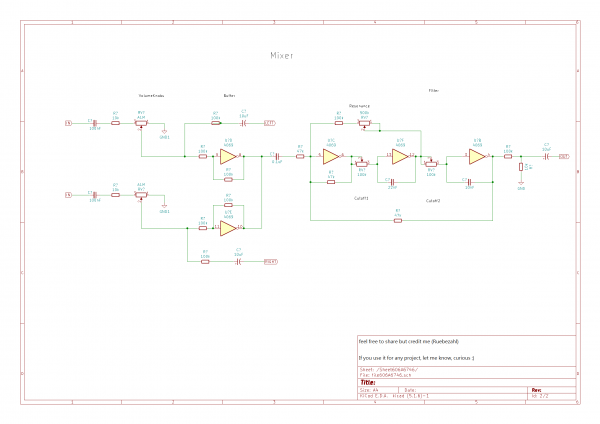
Here are the schematics, without any guarantee. I mean i built it and it works, but it's very possible there are some errors in the schematic, and i actually built it a bit different If you are a beginner and want to attempt something like this, i recommend just reading the original article on hackaday, and perhaps go through the whole series, it is really worthwile!
| Description: |
|
| Filesize: |
129.84 KB |
| Viewed: |
740 Time(s) |
| This image has been reduced to fit the page. Click on it to enlarge. |

|
| Description: |
|
| Filesize: |
61.39 KB |
| Viewed: |
588 Time(s) |
| This image has been reduced to fit the page. Click on it to enlarge. |
|
_________________
https://soundcloud.com/ruebezahl |
|
|
Back to top
|
|
|
Steveg

Joined: Apr 23, 2015
Posts: 184
Location: Perth, Australia
|
| Posted: Wed May 19, 2021 4:49 pm Post subject:
|
|
|
| It looks good and has a good array of sounds! |
|
|
Back to top
|
|
|
hexagon5un
Joined: Apr 10, 2009
Posts: 38
Location: Munich, Germany
Audio files: 1
|
Posted: Thu May 20, 2021 1:07 am Post subject:
Re: Logical Steps - patchable CMOS logic sequencer
Subject description: A sequencer based on 4051, 4040, 4093 CMOS technology |
|
|
... which in turn drew super-heavily on years and years of people's experience and experimentation here in the Lunetta forum at electro-music! So it all comes full circle.
Is there anything a 4051 can't do?
I love the two envelopes doing their thing over the sequence. That's tremendously musical and flexible for the tiny number of parts. Kudos! |
|
|
Back to top
|
|
|
Ruebezahl
Joined: Mar 09, 2014
Posts: 112
Location: Taiwan
Audio files: 4
|
Posted: Thu May 20, 2021 7:18 am Post subject:
Re: Logical Steps - patchable CMOS logic sequencer
Subject description: A sequencer based on 4051, 4040, 4093 CMOS technology |
|
|
| hexagon5un wrote: |
... which in turn drew super-heavily on years and years of people's experience and experimentation here in the Lunetta forum at electro-music! So it all comes full circle. |
Ah, wow it's you, isn't it Thanks for those articles! Of course it's not all new knowledge or something, we are talking about 50 year technology here after all, but the way it is written is very nice to understand, goes into detail, without being too overwelming. For me it kind of took off where Nicolas Collins book left me in terms of CMOS. It was not all new to me either, but it gave me a lot of new ideas, and things like a shift register or this Multiplexer i never got my head round before. Like i kind of knew what they do, but didn't really know how to use them. That changed now! 
| Quote: |
Is there anything a 4051 can't do? |
Still trying haha
| Quote: |
I love the two envelopes doing their thing over the sequence. That's tremendously musical and flexible for the tiny number of parts. Kudos! |
Thanks! yeah, i am really happy i decided for a Sawtooth output. That way the sawtooth sequence with less overtones can kind of ride in the back continueosly, and the bright pulse bursts out through the envelope occasionally
_________________
https://soundcloud.com/ruebezahl |
|
|
Back to top
|
|
|
wakyct
Joined: Dec 30, 2020
Posts: 105
Location: USA
Audio files: 12
|
| Posted: Sat May 22, 2021 9:42 am Post subject:
|
|
|
| I think the panel design looks really good, nice job! And thanks for pointing out those articles. |
|
|
Back to top
|
|
|
Ruebezahl
Joined: Mar 09, 2014
Posts: 112
Location: Taiwan
Audio files: 4
|
| Posted: Sat May 22, 2021 11:17 pm Post subject:
|
|
|
Thank you! Actually i just realized when you click the thumbnails they lead you to other thumbnails, instead of the big pictures. I fixed that, so now you should be able to properly see the frontplate (and where i messed up  ) )
_________________
https://soundcloud.com/ruebezahl |
|
|
Back to top
|
|
|
PHOBoS

Joined: Jan 14, 2010
Posts: 5884
Location: Moon Base
Audio files: 709
|
|
|
Back to top
|
|
|
Ruebezahl
Joined: Mar 09, 2014
Posts: 112
Location: Taiwan
Audio files: 4
|
| Posted: Wed May 26, 2021 2:13 am Post subject:
|
|
|
| PHOBoS wrote: | Nice clean layout and I love the colorful front. 
You get some nice sounds out of it too.
I am most intrigued by your blue alligator cables. I have only been able to get sets with white/black/red/yellow/green. |
Oh, thanks, that's nice hear that coming from you, because i am also very fond of your layout designs. I remember that moon base explorer, looking kind of like an old arcade machine, super cool!
The alligator clips, uhm, i actually made them myself, in my local electronic store they have the clips in the colors you mention + blue. So if you combine it with different colored cables, you can also make grey/red or yellow/purple or other funky combinations, for more variety.
That said, it's the first time i use alligator clips for patching and i am actually a bit annoyed by it, those rubber covers are often very "slippery", and keep sliding around the clips, when i try to press them, not sure if there is a work around. That my connectors are so thin and weak probably doesn't help either.
I found alligator clips that are much better in that regard, with hard plastic covers only over the part the fingers are pressing, but they only come in red and black, so it's not really possible to get a lot of different color combinations 
_________________
https://soundcloud.com/ruebezahl |
|
|
Back to top
|
|
|
PHOBoS
Joined: Jan 14, 2010
Posts: 5884
Location: Moon Base
Audio files: 709
|
| Posted: Wed May 26, 2021 9:43 am Post subject:
|
|
|
| Ruebezahl wrote: | | Oh, thanks, that's nice hear that coming from you, because i am also very fond of your layout designs. I remember that moon base explorer, looking kind of like an old arcade machine, super cool! |
thank you
I did notice some DIY cables because of the color combos but wasn't sure about the blue ones.
I wonder if they are actually available in some sets... oh adafruit has them: https://www.adafruit.com/product/1008
| Quote: | | That said, it's the first time i use alligator clips for patching and i am actually a bit annoyed by it, those rubber covers are often very "slippery", and keep sliding around the clips, when i try to press them, not sure if there is a work around. That my connectors are so thin and weak probably doesn't help either. |
Ah yes I've run into that before, covers slipping off all the time and rotating when you press them, I actually don't notice it so much these days.
Maybe it's mostly when they're still new and after a while the cover takes on a better shape or they get a bit dirty. There is variety of clips and cables out there,
I've had some tiny ones that would bend easily, some with very flexible cables while others are more rigid, some that have badly connected cables that come of
easy (it's not a bad idea to solder them and I've done that with a bunch of them) and I have some older ones of which the cover has become so hard they are
practically unusable. Overall I like them because they are pretty cheap and you don't need sockets which you'd need quite a lot of with these lunettas. No need
for mults either.
_________________
"My perf, it's full of holes!"
http://phobos.000space.com/
SoundCloud BandCamp MixCloud Stickney Synthyards Captain Collider Twitch YouTube
Last edited by PHOBoS on Sat May 29, 2021 8:39 pm; edited 1 time in total |
|
|
Back to top
|
|
|
NOISEBOB

Joined: Oct 13, 2019
Posts: 33
Location: NOISE
|
| Posted: Sat May 29, 2021 2:23 pm Post subject:
|
|
|
| alligator clips are great! |
|
|
Back to top
|
|
|
Ruebezahl
Joined: Mar 09, 2014
Posts: 112
Location: Taiwan
Audio files: 4
|
| Posted: Fri Jun 25, 2021 8:23 am Post subject:
|
|
|
| PHOBoS wrote: | | Ruebezahl wrote: | | Oh, thanks, that's nice hear that coming from you, because i am also very fond of your layout designs. I remember that moon base explorer, looking kind of like an old arcade machine, super cool! |
thank you
I did notice some DIY cables because of the color combos but wasn't sure about the blue ones.
I wonder if they are actually available in some sets... oh adafruit has them: https://www.adafruit.com/product/1008
| Quote: | | That said, it's the first time i use alligator clips for patching and i am actually a bit annoyed by it, those rubber covers are often very "slippery", and keep sliding around the clips, when i try to press them, not sure if there is a work around. That my connectors are so thin and weak probably doesn't help either. |
Ah yes I've run into that before, covers slipping off all the time and rotating when you press them, I actually don't notice it so much these days.
Maybe it's mostly when they're still new and after a while the cover takes on a better shape or they get a bit dirty. There is variety of clips and cables out there,
I've had some tiny ones that would bend easily, some with very flexible cables while others are more rigid, some that have badly connected cables that come of
easy (it's not a bad idea to solder them and I've done that with a bunch of them) and I have some older ones of which the cover has become so hard they are
practically unusable. Overall I like them because they are pretty cheap and you don't need sockets which you'd need quite a lot of with these lunettas. No need
for mults either. |
Yeah generally i think alligator clips have quite some advantages. They are also more easy to play intuitively and spontaniously. Like with my sequencer, i can momentarily play different rythms, by touching the clips to different connectors. You can't do that with patchcables, or you would be very busy
So, yeah, i hope my crocodiles will also wear down over time and become less annoying. One more reason to use the machine more, perhaps 
_________________
https://soundcloud.com/ruebezahl |
|
|
Back to top
|
|
|
Ruebezahl
Joined: Mar 09, 2014
Posts: 112
Location: Taiwan
Audio files: 4
|
| Posted: Fri Jun 25, 2021 8:34 am Post subject:
|
|
|
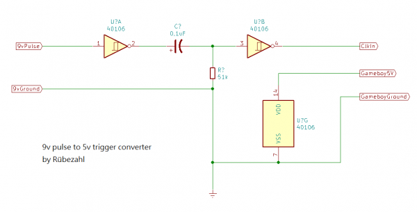
Ah, i also came up with a circuit to sync this sequencer with LSDJ. LSDJ needs short 5V pulses (15ms), as opposed to the 9V pulsewaves the CMOS chips put out. So i had to see how to lover the pulse to 5V and also if i need to make it shorter. I tried a lot with Voltage Divider, which didn't work at all. As soon as i turned on the gameboy, a clean pulse (between 0V and 3V, 5V, 4.5V or whatever) turned into a pulse that never really goes back to 0, oscillating between for example 0,3V and 3V or 0,6V and 5V, which didn’t really work anymore to trigger the clock of the gameboy. Seems like some resistance at the gameboy input seems to influence the voltage divider.
So i decided, since i still had to test if i can trigger the gameboy with pulsewaves instead of short triggers, to try something i can do with parts i have lying around. I created a clock from a 40106 schmitt trigger, but this time running the chip from the gameboy power supply's 5V. So i have a clean 5V pulsewave, that didn’t get compromised by the gameboys input. But it still didn’t properly keep the gameboy in sync, so i searched for a way to transform this pulse in a trigger of a certain length. I found a really simple solution by Ray Wilson (MFOS), which only consists of a resistor, capacitor and a schmitt trigger. So with the same chip i could build this gate to trigger converter. And after playing around with some values, i settled for a 0,1uF cap and a resistor of 50k (it worked down until 23k, but let’s play it safe). If the resistor is bigger it still worked (i checked until 500k), but the short pulse actually becomes a short oscillation (probably due to the simplicity of the design), so i sticked with 50k. I checked the length of the pulse and it is only around 5ms, much less than the 15ms of the volca series. So it seems LSDJ is not THAT picky after all
So this problem is solved, and it’s good to know the gameboy can actually power a chip through the link cable. But of course i won’t power my whole machine through the gameboy in the end, also because it runs on 9V. So i thought a feasible solution would be run a 40106 from the gameboy’s 5V, and feeding it a 9V pulse from my sequencer. Since the power supply of the chip is 5V it should give out a pulse of 5V instead, which i’d turn into a 5V trigger with the next inverter. It’s not the most economic version, and takes quite some space, and i still have 4 schmitt triggers left, but i could pull it off with parts i have lying around. And, yippieh, it works! (at least on the breadboard with a mockup sequencer clock, i yet have to connect it to my actual sequencer!)
Perhaps i could try a similar version with a transistor later. I could also imagine using the remaining inverters to do the opposite version, so i can have an clk in and clk out with one chip, but for that i would have to use a 4069 and power it from the 9v instead i guess...
| Description: |
|
| Filesize: |
9.85 KB |
| Viewed: |
243 Time(s) |
| This image has been reduced to fit the page. Click on it to enlarge. |
|
_________________
https://soundcloud.com/ruebezahl |
|
|
Back to top
|
|
|
Ruebezahl
Joined: Mar 09, 2014
Posts: 112
Location: Taiwan
Audio files: 4
|
| Posted: Mon Jun 28, 2021 4:40 am Post subject:
|
|
|
Oh, btw, after working on a tune with LSDJ and this machine and connecting them through the circuit i just showed here, i realized that the sequencer is going quite a bit slower when i connect it to the gameboy. as soon as i take out the cable, it's getting quicker again. We are talking about 20BPM give or take, quite a bit. It doesn't bother me too much at this moment, but i wonder why, and if i could fix it. I figure it is connected to the two power supplies somehow messing with each other, but not sure how to fix that. Input/output capacitors?
_________________
https://soundcloud.com/ruebezahl |
|
|
Back to top
|
|
|
kanebri
Joined: Apr 17, 2021
Posts: 10
Location: New Haven, CT
Audio files: 10
|
| Posted: Sat Jul 24, 2021 2:32 pm Post subject:
|
|
|
Fantastic job!
I really like the enveloping and filtering on it. I sometimes get tired of sequencers since repetition isn't really my musical thing. (To each their own.) I think the variations and longer durations due to the filters and envelopes make a big difference. A lot of nice sounds in a little box! |
|
|
Back to top
|
|
|
Ruebezahl
Joined: Mar 09, 2014
Posts: 112
Location: Taiwan
Audio files: 4
|
| Posted: Wed Oct 27, 2021 12:09 pm Post subject:
|
|
|
Thank you! Of course while playing with it, i mostly see the places where i could improve this machine, so it is good to hear that, and remind myself, that it's already quite some possibillities for such a small machine
_________________
https://soundcloud.com/ruebezahl |
|
|
Back to top
|
|
|
|

 Forum index » DIY Hardware and Software » Lunettas - circuits inspired by Stanley Lunetta
