| Author |
Message |
Estebandito
Joined: Dec 25, 2017
Posts: 33
Location: Amsterdam
Audio files: 3
|
|
|
Back to top
|
|
 |
Grumble

Joined: Nov 23, 2015
Posts: 1320
Location: Netherlands
Audio files: 30
|
|
|
Back to top
|
|
|
PHOBoS

Joined: Jan 14, 2010
Posts: 5888
Location: Moon Base
Audio files: 709
|
 Posted: Sat Dec 18, 2021 6:05 am Post subject: Posted: Sat Dec 18, 2021 6:05 am Post subject:
|
  |
|
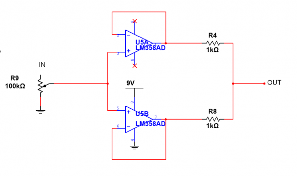
I first need to know what you are trying to achieve with the opamps, otherwise I might send you in the wrong direction.
Looking at the circuit diagram they are currently configured as comparators which could work for squarewaves or at least
the output would be a squarewave. The first one (U1G1) will invert the signal and the 100K resistor in the feedback path
could have added hysteresis if it was connected to the non-inverting input (pin 3). In the current configuration it could cause
some oscillations or more likely won't have any effect at all. The other opamp is configured as a non-inverting comparator.
Comparators switch state if the input voltage goes above or below the reference voltage. On U1G1 this reference voltage is set
at 4.5V with the 2 10K resistors, so if the input is below 4.5V the output will be 9V, if the input is above 4.5V the output will be 0V.
(note that the LM358 doesn't go fully up to 9V but can get pretty close to GND). If you're powering your logic chips with 5V it is
possible that the outputs will never get above 4.5V hence why nothing happens. If you set the reference votage lower, either by
decreasing the value of the 10K to GND or increasing the 10K connected to +9V, or even better connect it to +5V instead,
it should do something.
U1G2 has the reference voltage set to 4.9V but since it is driven by U1G1 it doesn't matter much at what voltage you set it.
_________________
"My perf, it's full of holes!"
http://phobos.000space.com/
SoundCloud BandCamp MixCloud Stickney Synthyards Captain Collider Twitch YouTube |
|
|
Back to top
|
|
|
Estebandito
Joined: Dec 25, 2017
Posts: 33
Location: Amsterdam
Audio files: 3
|
| Posted: Tue Dec 28, 2021 3:30 pm Post subject:
|
|
|
Thank you for taking the time to write a reply Phobos,
and sorry for replying to you late.
“If you're powering your logic chips with 5V it is
possible that the outputs will never get above 4.5V hence why nothing happens.”
I think that’s what is the matter.
I was looking for a simple amplification solution to help me boost the signal from a 5v powered cmos circuit before it goes to the volume pot and output jack. I have used a 386 before and that worked, but I had seen the 358 being used in lunetta designs and figured I would give that a go. Or rather, I lifted this circuit from elsewhere where it was indicated as the ‘amplifier section’ and tried to use it as an end stage amplifier by simply dropping it into my circuit without really knowing what I was doing (I should have known rushing to finish my design before the holidays was not a great idea). |
|
|
Back to top
|
|
|
PHOBoS
Joined: Jan 14, 2010
Posts: 5888
Location: Moon Base
Audio files: 709
|
| Posted: Wed Dec 29, 2021 8:07 am Post subject:
|
|
|
First of all the LM386 is not an opamp though it is usually drawn in the same way so keep that in mind. The LM358/LM324 is often used because it is
easily obtainable, cheap and most importantly it works well on a single supply since its output can practically go down to 0V. It's not the best opamp
for audio but for most purposes it will suffice.
If you have an output directly from a CMOS chip and everything is working on 5V you don't need any voltage amplification but buffering can be useful,
it depends on what you want to drive with it. If you want to connect it directly to a speaker you'll need to be able to drive a low impedance with a bit of
current which an LM386 is good at. A line input on the other hand should have a pretty high impedance (>10K) and also doesn't require much voltage,
5V would actually be too high. So you can just connect a potentiometer to the output of a CMOS chip and then connect it directly to a line input.
If you add a resistor between the CMOS output and the level pot it will limit the maximum voltage and at the same time protect the CMOS output
against any shorts. You could add an AC coupling capacitor after the pot but line inputs should already have those. If you want to connect it to another
circuit you will have to look at how things are biased and you may or may not need AC coupling.
If your signal comes from a resistor network (like an R2R) then it's better to buffer this first with an opamp configured as a voltage follower. You could also
use a transistor but that doesn't work so well if the voltage level is very low and you need some precision. You can also add a buffer after the level pot
which has the advantage that the output impedance stays constant and because it's also pretty low it is capable of driving more without causing a voltage drop.
| Quote: | | I lifted this circuit from elsewhere where it was indicated as the ‘amplifier section’ and tried to use it as an end stage amplifier by simply dropping it into my circuit without really knowing what I was doing (I should have known rushing to finish my design before the holidays was not a great idea). |
I've done a lot of cutting and pasting and it's how I learned most of what I know today. Over time you'll figure out why things are done a certain way
and it becomes easier to modify circuits to your own liking and design them from scratch.
_________________
"My perf, it's full of holes!"
http://phobos.000space.com/
SoundCloud BandCamp MixCloud Stickney Synthyards Captain Collider Twitch YouTube |
|
|
Back to top
|
|
|
Estebandito
Joined: Dec 25, 2017
Posts: 33
Location: Amsterdam
Audio files: 3
|
| Posted: Thu Dec 30, 2021 6:21 am Post subject:
|
|
|
Thanks again Phobos!
“So you can just connect a potentiometer to the output of a CMOS chip and then connect it directly to a line input.”
Apart from the opamp, the circuit is 100% cmos 4**** series, running on 5v. I had the output go straight to a potentiometer & output before, but I couldn’t use certain pedals or headphones, only active speakers. That’s why I figured I need some amplification.
Following your suggestion, I hooked up +5v as Vref and the lm358 is working now, but it sounds distorted (in a nice way, but I would prefer a clean amplification). Is this a limitation of the chip?
ps. I have used a lm386 with the following circuit before, but I didn't get much amplification. I might give this another try, as its output was clean. [img][/img]
| Description: |
|
| Filesize: |
71.96 KB |
| Viewed: |
310 Time(s) |
| This image has been reduced to fit the page. Click on it to enlarge. |

|
|
|
|
Back to top
|
|
|
Grumble
Joined: Nov 23, 2015
Posts: 1320
Location: Netherlands
Audio files: 30
|
| Posted: Fri Jan 07, 2022 3:14 pm Post subject:
|
|
|
I just don’t understand why you don’t use a circuit from the datasheet?
_________________
my synth |
|
|
Back to top
|
|
|
gabbagabi

Joined: Nov 29, 2008
Posts: 652
Location: Berlin by n8
Audio files: 23
|
|
|
Back to top
|
|
|
|

 Forum index » DIY Hardware and Software » Lunettas - circuits inspired by Stanley Lunetta