| Author |
Message |
synaesthesia

Joined: May 27, 2014
Posts: 291
Location: Germany
Audio files: 85
|
 Posted: Thu May 12, 2022 12:57 am Post subject: Posted: Thu May 12, 2022 12:57 am Post subject:
|
  |
|
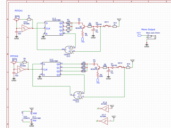
For manual triggers, you could leave away U1C, U1D, U2, U3A, U3D and the resistors/capacitors around them. You will still need a logic level at the points s1 and s2. Your triggers (positive) would go to the diodes. Look at the diagram in the lower right corner to see the sequence of triggers and the states of s1 and s2.
You can leave away the LM368 and get the output signal at the capacitor behind R12 and R13. They form a passive mixer with a rather strong signal. It might need some buffering, but not really amplification to go to a mixer. You could also send the individual signals from R12 and R13 to two mixer channels through individual capacitors. |
|
|
Back to top
|
|
 |
R_Gol
Joined: Oct 17, 2019
Posts: 34
Location: World
|
| Posted: Thu May 12, 2022 3:09 am Post subject:
|
|
|
| If I omit U2 what will cause the change of pitch? Is every new trigger with the manual button will change the pitch? |
|
|
Back to top
|
|
|
synaesthesia
Joined: May 27, 2014
Posts: 291
Location: Germany
Audio files: 85
|
| Posted: Thu May 12, 2022 5:17 am Post subject:
|
|
|
The logic levels at points s1 and s2 determine the pitch and timbre. To be more precise, those and the actual content of the shift registers in the very moment that their level changes. In the current implementation the counter U2 presents a static sequence of outputs, and their changes produce the triggers. The trigger sequence is static, but the actual sound they trigger may vary because the clock for the shift registers and the clock for the triggers are not synced.
| Code: | Example:
content is 0011 and s1 changes to 1 => the shift register will cycle through 0011,0111,1111,1110,1100,1000,0000,0001,0011,...
content is 0011 and s1 changes to 0 => the shift register will cycle through 0011,0110,1100,1001,0011,... |
|
|
|
Back to top
|
|
|
R_Gol
Joined: Oct 17, 2019
Posts: 34
Location: World
|
|
|
Back to top
|
|
|
synaesthesia
Joined: May 27, 2014
Posts: 291
Location: Germany
Audio files: 85
|
| Posted: Fri May 13, 2022 1:36 am Post subject:
|
|
|
| What you say is right, but the circuit will not work because input A of U3.3 is left floating. How do you intend to use the circuit and what are your inputs? |
|
|
Back to top
|
|
|
R_Gol
Joined: Oct 17, 2019
Posts: 34
Location: World
|
| Posted: Fri May 13, 2022 6:18 am Post subject:
|
|
|
| synaesthesia wrote: | | What you say is right, but the circuit will not work because input A of U3.3 is left floating. How do you intend to use the circuit and what are your inputs? |
I meant to connect input A of U3.3 after the button, just before the diode anode (same as in KEY1)
the original circuit generating a new note for pitch1 and pitch2 on every new clock of the TEMPO part of hte circuit. My intended is that on each manual pressing of KEY (either 1 or 2) a new tone will be generated. |
|
|
Back to top
|
|
|
synaesthesia
Joined: May 27, 2014
Posts: 291
Location: Germany
Audio files: 85
|
|
|
Back to top
|
|
|
R_Gol
Joined: Oct 17, 2019
Posts: 34
Location: World
|
|
|
Back to top
|
|
|
Steveg

Joined: Apr 23, 2015
Posts: 184
Location: Perth, Australia
|
| Posted: Sat May 14, 2022 2:34 am Post subject:
|
|
|
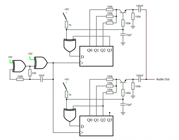
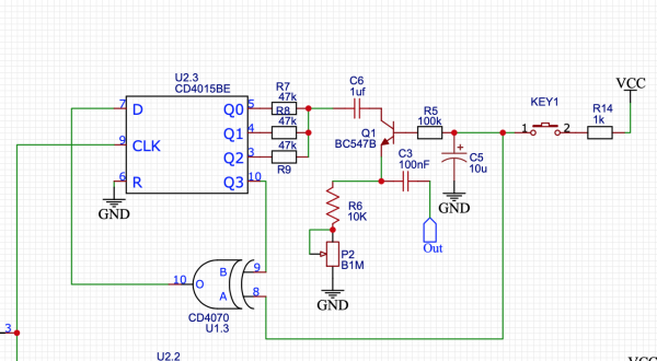
The two shift register taps cause differing frequencies. The one fed from Q3 is 1/8 the frequency of the oscillator. The other fed from Q2 is 1/6 of the oscillator.
Looped shift registers form a divider depending on which step is selected Q2 is the third step and Q3 is the fourth. The two XOR gates that are not part of the oscillator invert the output from the selected shift register stage diving the frequency by another two. hence 1/6 and 1/8. Don't be tempted to remove those XORs or you will have no output. |
|
|
Back to top
|
|
|
R_Gol
Joined: Oct 17, 2019
Posts: 34
Location: World
|
| Posted: Sat May 14, 2022 2:45 am Post subject:
|
|
|
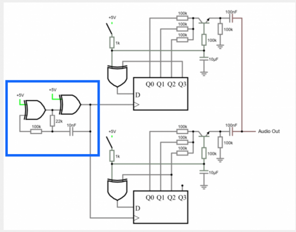
| What is the functionality of the two xor gates marked in blue? |
|
|
Back to top
|
|
|
Steveg
Joined: Apr 23, 2015
Posts: 184
Location: Perth, Australia
|
|
|
Back to top
|
|
|
R_Gol
Joined: Oct 17, 2019
Posts: 34
Location: World
|
|
|
Back to top
|
|
|
Steveg
Joined: Apr 23, 2015
Posts: 184
Location: Perth, Australia
|
| Posted: Sat May 14, 2022 4:25 am Post subject:
|
|
|
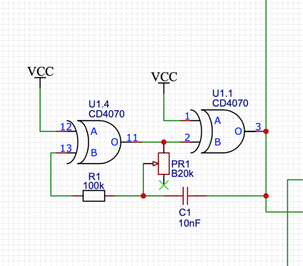
| Yes and yes. However the oscillator won't work at all if the pot resistance is too low. I don't have a good idea of where the cutoff will be but I would suggest putting a 10K resister in series with the pot. |
|
|
Back to top
|
|
|
R_Gol
Joined: Oct 17, 2019
Posts: 34
Location: World
|
| Posted: Sat May 14, 2022 4:28 am Post subject:
|
|
|
| Steveg wrote: | | Yes and yes. However the oscillator won't work at all if the pot resistance is too low. I don't have a good idea of where the cutoff will be but I would suggest putting a 10K resister in series with the pot. |
Thanks! will do so. Can't wait and try it tonight.
So changing the potentiometer shaft will change both tone generator fundamental frequency right? |
|
|
Back to top
|
|
|
Steveg
Joined: Apr 23, 2015
Posts: 184
Location: Perth, Australia
|
| Posted: Sat May 14, 2022 4:34 am Post subject:
|
|
|
| yep! |
|
|
Back to top
|
|
|
R_Gol
Joined: Oct 17, 2019
Posts: 34
Location: World
|
| Posted: Sat May 14, 2022 4:40 am Post subject:
|
|
|
Thanks.
What difference is it make if using 100k resistor from the shift registers Q outs instead of 47k as in the original schematics?
What will happen when using different values for each Q out? |
|
|
Back to top
|
|
|
Steveg
Joined: Apr 23, 2015
Posts: 184
Location: Perth, Australia
|
| Posted: Sat May 14, 2022 5:03 am Post subject:
|
|
|
| 100k vs 47k shouldn't matter much although 100k will pass lower frequencies on the emitter of the transistor. I think synaesthesia tried differing values elsewhere but found no value add. All it would do is make the output wave shape less regular. |
|
|
Back to top
|
|
|
R_Gol
Joined: Oct 17, 2019
Posts: 34
Location: World
|
| Posted: Sat May 14, 2022 5:37 am Post subject:
|
|
|
| How can I control the decay time of the tone generated? |
|
|
Back to top
|
|
|
synaesthesia
Joined: May 27, 2014
Posts: 291
Location: Germany
Audio files: 85
|
| Posted: Sat May 14, 2022 5:57 am Post subject:
|
|
|
Increasing the 10uF cap will increase the decay time. You can try 22uF or 100uF. However, it will take longer to load it through the resistor and switch to Vdd as well. So maybe it is better to increase the two 100K resistors to ground to 220K or 470K or even 1M.
Mind that the voltage at the cap in this circuit also is sensed by the XOR gates. So after the voltage falls to about Vdd/2 the frequence and/or timbre of the generated tone changes because the feeback path changes from inverting to non-inverting. |
|
|
Back to top
|
|
|
Steveg
Joined: Apr 23, 2015
Posts: 184
Location: Perth, Australia
|
| Posted: Sat May 14, 2022 6:00 am Post subject:
|
|
|
| Ah! I missed that. |
|
|
Back to top
|
|
|
R_Gol
Joined: Oct 17, 2019
Posts: 34
Location: World
|
|
|
Back to top
|
|
|
R_Gol
Joined: Oct 17, 2019
Posts: 34
Location: World
|
| Posted: Sat May 14, 2022 12:48 pm Post subject:
|
|
|
| synaesthesia wrote: | | You may want to try this on a breadboard. |
So I finally had the chance to try it. when I press on button 1 a certain pitch is generated and pressing on button 2 another different pitch is generated. so far so goof. When I pressing on those buttons once again, instead of generating a difference pitch, same pitch is generated. |
|
|
Back to top
|
|
|
Steveg
Joined: Apr 23, 2015
Posts: 184
Location: Perth, Australia
|
| Posted: Sat May 14, 2022 7:04 pm Post subject:
|
|
|
| It seems likely ... the pitch change should happen towards the end of the note not each note having a different pitch. |
|
|
Back to top
|
|
|
synaesthesia
Joined: May 27, 2014
Posts: 291
Location: Germany
Audio files: 85
|
| Posted: Sun May 15, 2022 1:52 am Post subject:
|
|
|
Add a potentiometer in series so the decay time could be changed?
The capacitor discharges through the transistor and the resistor to ground. Rather than exchanging the resistor to ground with a pot, try to replace the resistor to ground with a 10K and the resistor to the base with a 10K plus a 100K pot in series.
Why the same tone when I press the button?
While you press the button, the capacitor charges and the XOR gate acts as an inverter. The generated frequency will be low (twice the normal cycle length). Once you release the button and the capacitor voltage goes below the logic level throeshold for a HIGH, then the XOR will not invert any more and you have the chance of either doubling the frequency or getting silence.
If you want to have a different tone at the start, you could insert an inverter between the XOR and the input to the shift register. However, you then run the risk that you get no tone at the start and a high tone after some delay.
A better approach to create more variety in the tones is to double the clock speed and make the shift registers longer with a feedback after 6 or 8 bits.
The software I used for the circuit diagram is actually a circuit simulator: http://www.falstad.com/circuit/circuitjs.html |
|
|
Back to top
|
|
|
Steveg
Joined: Apr 23, 2015
Posts: 184
Location: Perth, Australia
|
| Posted: Mon May 16, 2022 3:06 am Post subject:
|
|
|
| synaesthesia wrote: | Add a potentiometer in series so the decay time could be changed?
The capacitor discharges through the transistor and the resistor to ground. Rather than exchanging the resistor to ground with a pot, try to replace the resistor to ground with a 10K and the resistor to the base with a 10K plus a 100K pot in series. |
I was going to say something similar and then I realised R_Gol has put the pot on the emitter of the transistor. In that position it probably will slow the discharge of the capacitor. |
|
|
Back to top
|
|
|
|

 Forum index » DIY Hardware and Software » Lunettas - circuits inspired by Stanley Lunetta