| Author |
Message |
moosapotamus

Joined: May 11, 2007
Posts: 113
Location: New Hampshire USA
|
 Posted: Wed Jan 04, 2023 10:25 am Post subject:
Single Cycle Mode for Baby-10 Sequencer Posted: Wed Jan 04, 2023 10:25 am Post subject:
Single Cycle Mode for Baby-10 Sequencer |
  |
|
Sorry, I know the 4017 has been beaten to death. But I haven't been able to search up an answer to this question...
I have a Baby-10 on my breadboard with only LEDs for now. I am clocking it with a 555 timer chip and all is well.
For easy ref... http://modular.fonik.de/pdf/baby10.pdf
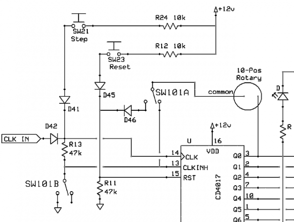
In addition, I have implemented a DPDT switch to go from 'normal' looping mode to single-cycle (arpeggio) mode. See SW101A/B in the attached drawing, below. SW101A/B is shown in single-cycle position.
Now, however many steps I have selected with the 10-Position rotary switch, when I switch from loop mode to single-cycle mode it stops on the next higher step. For example, if I set it to loop 5 steps, switching to single-cycle makes it stop on step 6. The reset button is properly triggering a single cycle, but it always stops on the next higher step.
The fact that it stops at the end of the cycle is okay, I guess, because it ensures that the first step will always fire at the beginning of a new single cycle. But I'm not sure how I feel about it stopping on the next higher step instead of the step number that I select with the rotary switch.
I haven't hooked up any gate outputs, yet, so I don't know how that last step is firing. Since the LED stays lit, I'll assume that it is holding the gate high, but I'm just guessing.
Overall, my main question is... Is there a better way to implement a single cycle mode with the 4017? And, what would be the preferred operation for a single cycle; stop on the same step as loop mode, stop at the end or beginning of the cycle, close the gate at the end of the cycle or leave it open, anything else to consider?
Thanks much for any help and/or insight!
| Description: |
| Single-Cycle mode switch (SW101A/B) for Baby-10 Sequencer |
|
| Filesize: |
41.64 KB |
| Viewed: |
121 Time(s) |
| This image has been reduced to fit the page. Click on it to enlarge. |
|
_________________
moosapotamus.net
"I tend to like anything that I think sounds good" |
|
|
Back to top
|
|
 |
moosapotamus
Joined: May 11, 2007
Posts: 113
Location: New Hampshire USA
|
| Posted: Thu Jan 05, 2023 9:54 am Post subject:
|
|
|
Also, when the rotary switch is set to loop 10 steps (common is unconnected), switching to single-cycle makes all the LEDs flash super fast (almost looks random) regardless of the clock tempo setting. I suppose I could just turn the rotary switch to position 9, as a work-around, to get it to do a single pass of 10 steps. But that just seems kinda lame.
So, still looking for the best way to implement a single pass mode. I'm really not that well versed with logic chips. Is it maybe just not possible with the 4017? Should I be using a different chip if I want to have that feature?
Thanks, again, for any advice.
_________________
moosapotamus.net
"I tend to like anything that I think sounds good" |
|
|
Back to top
|
|
|
PHOBoS

Joined: Jan 14, 2010
Posts: 5868
Location: Moon Base
Audio files: 709
|
| Posted: Mon Jan 09, 2023 8:16 am Post subject:
Re: Single Cycle Mode for Baby-10 Sequencer |
|
|
I was a bit confused by the way you connected to the CLK INH pin to the CLK input but I can see how you got there.
(will get back to that later)
| Quote: | | Now, however many steps I have selected with the 10-Position rotary switch, when I switch from loop mode to single-cycle mode it stops on the next higher step. For example, if I set it to loop 5 steps, switching to single-cycle makes it stop on step 6. The reset button is properly triggering a single cycle, but it always stops on the next higher step. |
yes, that makes sense. In both loop and single-cycle mode the same step triggers an event. In loop mode when you want 5 steps
you will have to connect reset to the 6th step. It does actually step through 6 steps but because it gets reset instantly it appears to only do 5.
In single-cycle mode it prevents the chip from stepping further once it reaches the 6th step by inhibiting the CLK.
So it will stay stuck on that step until the CLK INH pin goes low again which happens when you reset the chip.
| Quote: | | The fact that it stops at the end of the cycle is okay, I guess, because it ensures that the first step will always fire at the beginning of a new single cycle. But I'm not sure how I feel about it stopping on the next higher step instead of the step number that I select with the rotary switch. |
I can't think of an easy solution for that, it's just something to get used to. What is correct depends on how you label things.
You could label it to correspond with the single cycle-mode, so if you set it to the position labeled 6 it will stop at the 6th step.
Of course that means that in loop mode it will only step through 5 steps so you would always have to set the switch one position further
than the number of steps you want. But if you think about how the step you select is what triggers the reset than it's not so odd.
(After all it IS how the 4017 functions)
| Quote: | | I haven't hooked up any gate outputs, yet, so I don't know how that last step is firing. Since the LED stays lit, I'll assume that it is holding the gate high, but I'm just guessing. |
yes the output stays high which in turn inhibits the CLK input and prevents it from stepping further.
| Quote: | | Overall, my main question is... Is there a better way to implement a single cycle mode with the 4017? And, what would be the preferred operation for a single cycle; stop on the same step as loop mode, stop at the end or beginning of the cycle, close the gate at the end of the cycle or leave it open, anything else to consider? |
you have some options for the gate output. In the Fonik one you linked gate2 is converted to a short trigger pulse.
As a result it will give a short pulse for each step that is selected (SW11~SW20) and doesn't stay high when the 4017 stops counting.
Another way to implement this is to use an AND gate for the gate output and as inputs for it use the gate2 signal and the clock signal.
The result is that the gate output stays high as long as the clock input is high. This allows for adjusting the gate length with the duty cycle of the clock.
The other gate output in the schematic is will stay high during the full step length for every selected step.
So if you would set it to hold in step 6 and you also turn on the gate for step 6 it will just stay on.
I think there would be a way to prevent this by adding a flip flop,. or maybe you'd need one per step (haven't given it much thought yet)
************************
| moosapotamus wrote: | | Also, when the rotary switch is set to loop 10 steps (common is unconnected), switching to single-cycle makes all the LEDs flash super fast (almost looks random) regardless of the clock tempo setting. I suppose I could just turn the rotary switch to position 9, as a work-around, to get it to do a single pass of 10 steps. But that just seems kinda lame. |
There is an error in your schematic.
the CLK input (pin14) has 2 diodes (D41/D42) and a resistor (R13) connected to it, these form a logic OR gate so that you can use the Step switch or the CLK IN
or both at the same time without creating any electrical shorts. However for this to function the other side of R13 should be connected to GND.
Currently you severed that connection in single-cycle mode with SW101B. If the rotary switch is set to loop less than 10 steps then R13 has another path
to GND through that switch and the outputs of the 4017 which are low.
To correct this:
disconnect R13 from SW101B and the CLK INH pin and connect it directly to GND
add another (47K) resistor from the CLK INH pin to GND
you don't need SW101B anymore
if you now set it to 10 steps (common is unconnected) it will just keep running as there is no signal to inhibited the CLK (you'd need an 11th step)
| Quote: | | So, still looking for the best way to implement a single pass mode. I'm really not that well versed with logic chips. Is it maybe just not possible with the 4017? Should I be using a different chip if I want to have that feature? |
The 4017 (+555) is often used to create a sequencer because it is so simple to build. However it is also very limited.
If you want more features it makes sense to design a sequencer around a binary counter and then convert it.
So with 3 bits you can get up to 8 steps, with 4 bits you can get to 16 steps.
This will require more chips and, depending on the design, some might be difficult to get.
Or you could go a with a microcontroller like an arduino which will be the smallest and most versatile option, but where's the fun in that.
also: https://electro-music.com/forum/topic-63020.html
_________________
"My perf, it's full of holes!"
http://phobos.000space.com/
SoundCloud BandCamp MixCloud Stickney Synthyards Captain Collider Twitch YouTube |
|
|
Back to top
|
|
|
moosapotamus
Joined: May 11, 2007
Posts: 113
Location: New Hampshire USA
|
| Posted: Mon Jan 09, 2023 5:44 pm Post subject:
|
|
|
Thank you so much for all your comments and suggestions!
I am running the 555 clock through one of the gate to trigger converters, as in Fonik's scheme, and I tried connecting the Gate2 bus to the other and got no output. Probably my fault. I am planning to try using and AND gate instead, but I've signed off for tonight and I don't have any of those in my stash, yet (on order).
For the single cycle mode, I had to disconnect Pin 13 from ground to get it to work but, again, probably something else going on that I wasn't aware of. I'm going to try implementing is as you did in the Little Gate (thanks for the link, BTW).
I set up a few pots on my breadboard to test the CV output and that seems to be working well. Planning to have two channels of gates and CV as in the Baby 10, and then add a sequential switch for even more fun.
Thanks again for the help. I'll post results when I get things working as they should.
_________________
moosapotamus.net
"I tend to like anything that I think sounds good" |
|
|
Back to top
|
|
|
|

 Forum index » DIY Hardware and Software
