| Author |
Message |
lytex
Joined: Jun 20, 2025
Posts: 3
Location: universe
|
 Posted: Fri Jun 20, 2025 9:41 am Post subject:
Help debugging Lunetta/Klangorium circuit (custom PCB) Posted: Fri Jun 20, 2025 9:41 am Post subject:
Help debugging Lunetta/Klangorium circuit (custom PCB) |
  |
|
Hi! This is my first post 
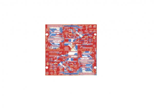
After having soldered and played with a klangorium, I'm designing my very first PCB, called kleingorium. It is a selectable frequency divider/multiplier, which depending whether the Select input is low or high, divides or multiplies the frequency (schematics here)
The frequency division/multiplication uses a 4017 decade counter with or without feedback from a 4046 PLL, and then multiplies or divides the input with a 4040 so that the frequency stays in the same octave, using the after mentioned 4046.
To achieve the selection, I'm using a 4053 and half a 4066. The circuit is symmetric and the 4066 is shared, so the top half is almost the same circuit, and you can chain them via another switch (Chain). I have only soldered the bottom half.
I also have a switch to disconnect the 4046 feedback loop (4046 CompIn), and another switch to select 4017 Q0 or 4017 Reset pins (4017 Fdbk).
This is the simplified schematic, showing each path connected with wires, instead of 4066/4053, on the top the circuit with Select = 0 and bottom circuit is Select = 1:

The issue is as follows:
Select = 0, 4017 Fdbk = Reset works ok, but Select = 0, 4017 Fdbk = Q0 does not
Select = 1, 4017 Fdbk = Q0 works ok, but Select = 1, 4017 Fdbk = Reset does not
I'm feeding the Kleingorium (my board) with a 40106 oscillator from the Klangorium. To solve it, I have found the following hacks:
- Connect the faulty output, either Q0 or Reset, to a oscillating 40106. The higher the frequency, the better it works
- Connect the faulty output to a slow oscillating 4040. When the output is high, it sounds ok, which motivated my next approach:
- Connect the faulty output with a small pull-up to VCC (i'm using 9V supply). To solve Select=0, 4017 Fdbk=Q0, I need a 310ohm pull-up or less (even 0 ohm works), and to solve Select=1, 4017 Fdbk=Reset, I need a pull-up between 260ohms and 1k. I have this solution currently on the schematics as trimpots: RV1, RV2, RV3, RV4
Possible ideas:
- Not enough track width
- Floating legs adding noise, crosstalk, etc
- Unconnected paths via 4066 or 4053 adding also noise
- Something with the 4046 feedback loop doing weird things? It's the most critical part of the circuit
| Description: |
| Simplified schematic showing the feedback design of the module |
|
| Filesize: |
69.27 KB |
| Viewed: |
4 Time(s) |
| This image has been reduced to fit the page. Click on it to enlarge. |

|
| Description: |
|
| Filesize: |
212.56 KB |
| Viewed: |
8 Time(s) |
| This image has been reduced to fit the page. Click on it to enlarge. |

|
| Description: |
|
| Filesize: |
217.07 KB |
| Viewed: |
3 Time(s) |
| This image has been reduced to fit the page. Click on it to enlarge. |
|
|
|
|
Back to top
|
|
 |
lytex
Joined: Jun 20, 2025
Posts: 3
Location: universe
|
| Posted: Sun Jun 22, 2025 1:58 am Post subject:
Re: Help debugging Lunetta/Klangorium circuit (custom PCB) |
|
|
I have done some more debugging:
With Select=0, 4017 Fdbk=Reset, the feedback from 4017 Reset to 4046 Cmp won't work unless the resistance is lower than 100 ohms for the PLL to lock in. The 4053 datasheet says that the resistance between connected paths is 180 ohms at 10V, so there is a possible explanation. However I don't understand why connecting a pull-up resistor to Reset would result in less resistance.
(edit) In the case Select=1, 4017 Fdbk=Q0, even connecting the selected circuit with cables doesn't work, there is some noise leaking in. However, placing a pull-down on A1 (which is a supposedly unconnected path leading to 4017 reset) in the range 920 to 2 ohms eliminates the noise |
|
|
Back to top
|
|
|
Cynosure
Site Admin

Joined: Dec 11, 2010
Posts: 999
Location: Toronto, Ontario - Canada
Audio files: 82
|
| Posted: Tue Jun 24, 2025 8:43 am Post subject:
|
|
|
I am having difficulty following your schematic. It looks like the 4053 is either sending Q0 from the 4017 to the 4046 input, or sending the reset input of the 4017 to the input of the 4046. At first, I thought that maybe you intended to send the Q0 to the reset instead, but that would just set the 4017 so that it doesn't output anything at all. Maybe you intended to send the Q1 to the reset pin?
A clearer schematic would help, but I think that you might have to review how that 4053 switch is working because you are sending an input to an input.
_________________
JacobWatters.com |
|
|
Back to top
|
|
|
lytex
Joined: Jun 20, 2025
Posts: 3
Location: universe
|
| Posted: Tue Jun 24, 2025 1:04 pm Post subject:
|
|
|
| Right, the 4017 reset is an input so if you don't connect anything then the PLL is floating. What I do to get a sound is connect some output of the 4017 to the reset pin with a dupont cable, and then it starts to sound. |
|
|
Back to top
|
|
|
|

 Forum index » DIY Hardware and Software » Lunettas - circuits inspired by Stanley Lunetta

