| Author |
Message |
synthmonger
Joined: Nov 16, 2006
Posts: 578
Location: flada
Audio files: 3
|
|
|
Back to top
|
|
 |
synthmonger
Joined: Nov 16, 2006
Posts: 578
Location: flada
Audio files: 3
|
 Posted: Mon Sep 08, 2008 11:55 pm Post subject: Posted: Mon Sep 08, 2008 11:55 pm Post subject:
|
  |
|
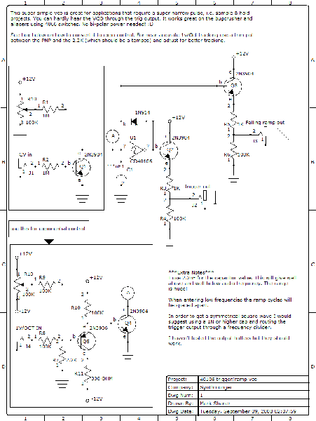
| Err there's an error in the schematic. The linear cv should be +9 volt not +12. It'll work on 12 but you'll have to change some values I'm sure. |
|
|
Back to top
|
|
|
slabman
Joined: Sep 01, 2005
Posts: 102
Location: UK
|
| Posted: Tue Sep 09, 2008 2:02 pm Post subject:
Nice! |
|
|
| Thanks for sharing this. Looks like a great way to munge together a Weird Sound Generator with a Soundlab. |
|
|
Back to top
|
|
|
synthmonger
Joined: Nov 16, 2006
Posts: 578
Location: flada
Audio files: 3
|
| Posted: Tue Sep 09, 2008 2:53 pm Post subject:
|
|
|
| bunch more uses of the 40106 on the way. |
|
|
Back to top
|
|
|
Rykhaard
Joined: Sep 02, 2007
Posts: 1290
Location: Canada
|
| Posted: Tue Sep 09, 2008 9:33 pm Post subject:
|
|
|
| synthmonger wrote: | | bunch more uses of the 40106 on the way. |
Even more uses for the 25 that I recently bought?  Thanks Ray Wilson for influencing me on this chip! Thanks Ray Wilson for influencing me on this chip! 
Can't wait to get finished moving my studio around, so that I can get back to experiments for the Liquid Hihat and new experiments with the CD40106! |
|
|
Back to top
|
|
|
scriptstyle

Joined: Jan 22, 2008
Posts: 250
Location: nj
|
| Posted: Sun Sep 14, 2008 5:44 pm Post subject:
|
|
|
| i bread boarded this up the other day on 5v. and got nothing i think im going to try and knock down the 1m's to 100k and see what happens? excited to get a tri out of a 40106 though!! |
|
|
Back to top
|
|
|
synthmonger
Joined: Nov 16, 2006
Posts: 578
Location: flada
Audio files: 3
|
| Posted: Sun Sep 14, 2008 11:50 pm Post subject:
|
|
|
I was using 9V and 12V. Not sure if 5V will work.
The linear portion really isn't linear and only have a range of a couple volts. Make sure you're connections and transistors are facing the right way, I'm 100% certain this works. |
|
|
Back to top
|
|
|
scriptstyle
Joined: Jan 22, 2008
Posts: 250
Location: nj
|
| Posted: Mon Sep 15, 2008 11:09 pm Post subject:
|
|
|
| got it going i had a 2n reversed. very cool thanks!! |
|
|
Back to top
|
|
|
synthmonger
Joined: Nov 16, 2006
Posts: 578
Location: flada
Audio files: 3
|
| Posted: Sat Oct 11, 2008 11:16 am Post subject:
|
|
|
| Remove C1 and add trim pot on the negative end of the manual voltage control to get a high frequency vco. |
|
|
Back to top
|
|
|
Pehr

Joined: Aug 14, 2005
Posts: 1307
Location: Björkvik, Sweden
Audio files: 2
|
|
|
Back to top
|
|
|
synthmonger
Joined: Nov 16, 2006
Posts: 578
Location: flada
Audio files: 3
|
| Posted: Tue Oct 21, 2008 2:41 am Post subject:
|
|
|
| Pehr wrote: | | is there any chance of getting exponential control with single supply psu? |
Still working on that. I tried using an expo the way fonik did in his wasp edp but no luck. |
|
|
Back to top
|
|
|
scriptstyle
Joined: Jan 22, 2008
Posts: 250
Location: nj
|
| Posted: Sun Mar 15, 2009 4:13 pm Post subject:
|
|
|
| Ok so I looking at this cuircuit again the other day. On a 5v supply I changed r1 to 10m, and c1 needs to be atleast .22uf. Now I was using a .22uf Mylar cause it was the biggest I had on hand. This gave me a frequency of about 1.6k hz. I wanted more freq I tried a 1uf electro and the top end of the ramp rounds out? Is this because the electro cap? I'm going to be making a local run to a shop that has polystyrene caps in higher numbers. Maybe this is what I need... |
|
|
Back to top
|
|
|
synthmonger
Joined: Nov 16, 2006
Posts: 578
Location: flada
Audio files: 3
|
| Posted: Mon Mar 16, 2009 2:02 pm Post subject:
|
|
|
| scriptstyle wrote: | | Ok so I looking at this cuircuit again the other day. On a 5v supply I changed r1 to 10m, and c1 needs to be atleast .22uf. Now I was using a .22uf Mylar cause it was the biggest I had on hand. This gave me a frequency of about 1.6k hz. I wanted more freq I tried a 1uf electro and the top end of the ramp rounds out? Is this because the electro cap? I'm going to be making a local run to a shop that has polystyrene caps in higher numbers. Maybe this is what I need... |
I haven't tested this on a 5V supply to be honest with ya. If I can find some time later I will test it out. A bit busy building a 100% lunetta vco right now.
What application are you using it for? |
|
|
Back to top
|
|
|
scriptstyle
Joined: Jan 22, 2008
Posts: 250
Location: nj
|
| Posted: Mon Mar 16, 2009 2:14 pm Post subject:
|
|
|
| I'm building my lunetta almost as like a 5v CMOS learning lab. I should prototyping cause nothing has made it off the breadboard or off cardboard yet. I may re concider 12v? Idk.... |
|
|
Back to top
|
|
|
Rykhaard
Joined: Sep 02, 2007
Posts: 1290
Location: Canada
|
| Posted: Mon Mar 16, 2009 6:10 pm Post subject:
|
|
|
| scriptstyle wrote: | | I'm building my lunetta almost as like a 5v CMOS learning lab. I should prototyping cause nothing has made it off the breadboard or off cardboard yet. I may re concider 12v? Idk.... |
My Lunetta ..... monster, is so far running beautifully from +/-9VDC. |
|
|
Back to top
|
|
|
scriptstyle
Joined: Jan 22, 2008
Posts: 250
Location: nj
|
| Posted: Mon Mar 16, 2009 7:05 pm Post subject:
|
|
|
| So ryk you are using 9v? Synthmonger is using 12v. I honestly thought you where using 12v also. I keep hearing using 12v will make of easier to intergreat to my modular. But what iwas thinking was that. I will have any easier time seeing what the CMOS is doing on 5v? |
|
|
Back to top
|
|
|
scriptstyle
Joined: Jan 22, 2008
Posts: 250
Location: nj
|
| Posted: Mon Mar 16, 2009 7:28 pm Post subject:
|
|
|
| Something occured to me just now while reading the thread you just started about using a 4007's gates. This is my secound time working with this schematic and the last time I remember geting a good range of osc with a cap around 1n, but like I mentioned earlier ihad no such luck this time. Just high freq osc. Then I remembered I did have a pullup resistor before c1 the first time around. Should that make the difference? |
|
|
Back to top
|
|
|
Rykhaard
Joined: Sep 02, 2007
Posts: 1290
Location: Canada
|
| Posted: Mon Mar 16, 2009 7:36 pm Post subject:
|
|
|
| scriptstyle wrote: | | So ryk you are using 9v? Synthmonger is using 12v. I honestly thought you where using 12v also. I keep hearing using 12v will make of easier to intergreat to my modular. But what iwas thinking was that. I will have any easier time seeing what the CMOS is doing on 5v? |
The most important thing to me for running my machine, were the ability to run it from batteries as well. That, ruled out running my machine from +/-15V.
Also, the voltage limit for CMOS chips, depending on the chip type is +18 or +20V.
So - to make sure that I could run all of the CMOS chips that I would be using, I thought it better to operate the system on the +18 / 2 voltage, or +/- 9VDC. I just happened to have 7809 and 7909 1 amp voltage regulators that I had purchased in the early 90's as well.
That, will allow me to run my system from 2 x 12V batteries hooked up in the +/- format, as well as interface to my modular's +/- 15V, as long as I don't let anything higher or lower than 9V into my Lunetta machine.
I've been doing ok so far. |
|
|
Back to top
|
|
|
ashaxx
Joined: Jun 15, 2009
Posts: 7
Location: uk
|
| Posted: Fri Sep 04, 2009 5:38 am Post subject:
vco |
|
|
| sorry for such an amatuer question here but is the Circled A the audio out? |
|
|
Back to top
|
|
|
jean-louise

Joined: Apr 27, 2009
Posts: 73
Location: berlin
Audio files: 2
|
| Posted: Fri Sep 04, 2009 8:41 am Post subject:
Re: vco |
|
|
| ashaxx wrote: | | sorry for such an amatuer question here but is the Circled A the audio out? |
no, i think it's just the point where either the linear or expo CV input are connected to the circuit
jan |
|
|
Back to top
|
|
|
slacker
Joined: Nov 18, 2007
Posts: 301
Location: England
Audio files: 11
G2 patch files: 1
|
| Posted: Fri Sep 04, 2009 10:07 am Post subject:
|
|
|
Yeah that's right it's just the point where you connect either of the converters. The audio out is the "Falling ramp out".
You could technically use point A as an audio out providing that what ever you connected it to had a high input impedance, otherwise it would load the input of the inverter and stop it oscillating. That's basically what Q3 is already doing in the circuit. |
|
|
Back to top
|
|
|
Psyingo

Joined: Jun 11, 2009
Posts: 248
Location: Canada
|
| Posted: Sun Sep 13, 2009 9:59 pm Post subject:
|
|
|
| I boarded one of these and it's really great. thanks for posting a schematic. I enjoy your circuits, synthmonger. |
|
|
Back to top
|
|
|
synthmonger
Joined: Nov 16, 2006
Posts: 578
Location: flada
Audio files: 3
|
| Posted: Mon Sep 14, 2009 4:10 pm Post subject:
|
|
|
By the way, use an op-amp buffer on the 'sawtooth' output. 4069 inverter gates would probably do the trick too. This gives it better if not perfect symmetry.
_________________
Youtube!
modular demos!
Whacky tunes! |
|
|
Back to top
|
|
|
synthmonger
Joined: Nov 16, 2006
Posts: 578
Location: flada
Audio files: 3
|
| Posted: Mon Sep 14, 2009 7:14 pm Post subject:
|
|
|
Oh and if ya plan to build multiple VCOs out of one chip I'd limit it to a max of 4 so they won't bleedthrough/modulate each other. Keep the middle inverters grounded.
I like to stick with two VCOs in a single chip. I use three inverters wired in series with the first two for the sync input and the last one as the vco core.
Oh and I found a neat way of getting 1-100% PWM using 3 gates. It sounds pretty different than you're typical op-amp pwm configuration.
...I should spend some time posting schematics for these...
_________________
Youtube!
modular demos!
Whacky tunes! |
|
|
Back to top
|
|
|
Psyingo
Joined: Jun 11, 2009
Posts: 248
Location: Canada
|
| Posted: Mon Sep 14, 2009 8:12 pm Post subject:
|
|
|
| yes please, moar schematics! |
|
|
Back to top
|
|
|
|

 Forum index » DIY Hardware and Software » Lunettas - circuits inspired by Stanley Lunetta