| Author |
Message |
frijitz
Joined: May 04, 2007
Posts: 1734
Location: NM USA
Audio files: 54
|
 Posted: Fri Aug 27, 2010 6:01 pm Post subject: Posted: Fri Aug 27, 2010 6:01 pm Post subject:
|
  |
|
| Funky40 wrote: | | I never found it more interesting or musical to patch two teezers than a teezer and another highfrequenzyrange VCO. |
Could you clarify that? What exactly can you do with the other VCO that you couldn't do with a second Teezer?

Ian |
|
|
Back to top
|
|
 |
Luka

Joined: Jun 29, 2007
Posts: 1003
Location: Melb.
|
| Posted: Sat Aug 28, 2010 12:55 am Post subject:
|
|
|
| frijitz wrote: | | Luka wrote: | | which results in that list in particular dont make sense? |
u2-2: I don't see how this could be varying with the frequency control.
u2-3: I don't see how this could possibly be near -11V. (u2 is powered by +/-7V, R29 is connected to +5V, etc.)
Sorry, this is completrely crazy.
Ian |
Hi Ian
Im trying to solve this problem again.
Following your procedure listed in previous pages
expo looks ok
A2-6 is steady at -3.36
U2-2 0.53
U2-3 1.11
U2-7 -6.8
U3-2 -4.3
U3-3 -4
U3-7 -5.69
do they look ok?
_________________
problemchild
melbourne australia
http://cycleofproblems.blogspot.com/
http://www.last.fm/user/prblmchild |
|
|
Back to top
|
|
|
frijitz
Joined: May 04, 2007
Posts: 1734
Location: NM USA
Audio files: 54
|
| Posted: Sat Aug 28, 2010 1:45 am Post subject:
|
|
|
| Luka wrote: | Im trying to solve this problem again.
Following your procedure listed in previous pages
expo looks ok
A2-6 is steady at -3.36
U2-2 0.53
U2-3 1.11
U2-7 -6.8
U3-2 -4.3
U3-3 -4
U3-7 -5.69 |
Hi Luka --
A2-6 is the oscillator output. For some reason it can't ramp all the way down to -5V. Most likely is that one or both of the FETs Q4/Q5 is buzzed. These are very easy to damage with too much heat while soldering or by static. So next try replacing them both. Make sure you stay grounded, and leave the leads longish. Solder quickly, preferably with a clip on the lead to dissipate heat.
Ian |
|
|
Back to top
|
|
|
Luka
Joined: Jun 29, 2007
Posts: 1003
Location: Melb.
|
|
|
Back to top
|
|
|
frijitz
Joined: May 04, 2007
Posts: 1734
Location: NM USA
Audio files: 54
|
| Posted: Sat Aug 28, 2010 2:42 am Post subject:
|
|
|
| Luka wrote: | | damn guess ill have to order some more of those |
Well, it could be something else, but that's where I would start. At least they're not too expensive.
| Quote: | i actually have the fets placed in pin sockets
they were never soldered directly |
That's a real good idea. You could pull them and try them in a test circuit to see if they are good or not. Or try replacing them with some generic MOSFET -- you should at least get some oscillations (I think).
Ian |
|
|
Back to top
|
|
|
Luka
Joined: Jun 29, 2007
Posts: 1003
Location: Melb.
|
|
|
Back to top
|
|
|
frijitz
Joined: May 04, 2007
Posts: 1734
Location: NM USA
Audio files: 54
|
| Posted: Sat Aug 28, 2010 6:09 pm Post subject:
|
|
|
| Luka wrote: | | ian i swapped the mosfets from my working teezers into this one and it made no difference. what would be the next section to check? |
Hmmm ... hard to know where to start.
1...Check whether A2, pin 6 changes at all as you move the Init control from end to end. Check with a scope probe to see if there are small hf oscillations there.
2...Are you using LM311's from the same supplier as on the other boards?
3...Measure the voltage at the node where D2, D6, et al come together.
Let's start with those.
Ian |
|
|
Back to top
|
|
|
Luka
Joined: Jun 29, 2007
Posts: 1003
Location: Melb.
|
|
|
Back to top
|
|
|
Luka
Joined: Jun 29, 2007
Posts: 1003
Location: Melb.
|
| Posted: Wed Sep 08, 2010 5:10 am Post subject:
|
|
|
well as smart as i thought i was by using pin connectors on the transistors they were my downfall in this case. the bass of the connector was shorting pin 2 to pin 3 of A2 ie to ground.
i just de-soldered the area and put it back together and it is up and running
a good way to finish a frustrating day
_________________
problemchild
melbourne australia
http://cycleofproblems.blogspot.com/
http://www.last.fm/user/prblmchild |
|
|
Back to top
|
|
|
Funky40
Joined: Sep 24, 2005
Posts: 875
Location: Swiss
Audio files: 1
G2 patch files: 5
|
| Posted: Mon Sep 13, 2010 1:30 am Post subject:
|
|
|
| frijitz wrote: |
Could you clarify that? What exactly can you do with the other VCO that you couldn't do with a second Teezer?
|
nothing ofcourse.
a teezer is a very fine modulationsource.
but it's in my opinin not necessary to have two Thru Zero VCOs in one package.
sorry for not being clear enough. |
|
|
Back to top
|
|
|
tomcat
Joined: Oct 14, 2005
Posts: 141
Location: earth
|
| Posted: Sat Oct 23, 2010 10:31 pm Post subject:
Re: Dual Teezer module? |
|
|
| frijitz wrote: |
Well, yes! Scott at bridechamber and I are working on a dual version in euro format. I wanted to do it without changing the board layout significantly, so I just shrunk it down a bit and added the extra power connector. Scott is working on the challenge of designing mounting brackets -- it's going to be a tight squeeze.
We haven't talked about cross-connections yet, but it seems to me it would be easy to normalize some connections on the panel, without changing the board.
Ian |
News about this project? |
|
|
Back to top
|
|
|
Terrafractyl
Joined: Sep 21, 2010
Posts: 13
Location: Melbourne
|
| Posted: Tue Jul 12, 2011 1:06 am Post subject:
|
|
|
Hm I thought I already posted something here and it dissapeared... strange, ah well I'll try again!
So i've just finished putting together a Teezer, and on powering it up it works(all outputs), but only as long as I have the Initial Frequency pot above 12 o'clock.
As soon as it goes below, it kind of dies and I get nothing from any of the outputs until either I, power down, turn up the initial freq pot and power up the Teezer... or if I put a signal into the sync input it also kick starts the oscillations.
I'm using a kit from bridechamber and I used Dave Browns 15v resistor/diode mod.
All the IC's seem to be getting the correct power, + - 7v on U2 and 3 and +-9v on the A4
I checked the output of A3-6 and it swings from +5 to -5v fine.
I checked A2-6 output and it mesures +2.5 when the Oscillator is giving me sound and +5.0v when it has gone silent. Also the outputs all give me +5.0v when the oscillator is silent.
I checked the node where D2, D4, D6 etc join and when the Oscillator is working I get a -6.3v but when the Oscillator has gone silent I get a 3.5v
I only have software scope, but the saw has a very sharp downward peak just before the top of the waveform, and the sinewave is round at the top and triangular on the bottom.
So I have a feeling that it might be something to with either one of the LM311's or one of the VN0104's. but any help would be greatly appreciated.
Even without the Through zero, and with the problems it has, its sounds great already, I cant wait to get it working properly! |
|
|
Back to top
|
|
|
frijitz
Joined: May 04, 2007
Posts: 1734
Location: NM USA
Audio files: 54
|
| Posted: Tue Jul 12, 2011 1:36 pm Post subject:
|
|
|
| Terrafractyl wrote: | ...So i've just finished putting together a Teezer, and on powering it up it works(all outputs), but only as long as I have the Initial Frequency pot above 12 o'clock.
As soon as it goes below, it kind of dies and I get nothing from any of the outputs until either I, power down, turn up the initial freq pot and power up the Teezer... or if I put a signal into the sync input it also kick starts the oscillations. |
Ouch! Sorry you are having trouble. Thanks for getting a start on the troubleshooting -- that helps a bunch.
To make sure I'm clear, you can only ever get an upramp? IOW, you can not jumpstart the downramp?
| Quote: | I checked A2-6 output and it mesures +2.5 when the Oscillator is giving me sound and +5.0v when it has gone silent. Also the outputs all give me +5.0v when the oscillator is silent.
I checked the node where D2, D4, D6 etc join and when the Oscillator is working I get a -6.3v but when the Oscillator has gone silent I get a 3.5v |
Could you please check the output voltages (pin 7) of U2 and U3 when the system is stalled?
My guess is that one of the VN0104 MOSFETs is buzzed. The are very sensitive to both heat and static -- I've buzzed a few myself. So if you have checked everything carefully (correct parts and orientation, no solder bridges) then the first thing to try would be to replace Q4 and Q5. Carefully -- leave the leads a bit longish and solder quickly.
| Quote: | | Even without the Through zero, and with the problems it has, its sounds great already, I cant wait to get it working properly! |
Good. I hope the problem is simple.
Ian |
|
|
Back to top
|
|
|
emdot_ambient
Joined: Nov 22, 2009
Posts: 667
Location: Frederick, MD
|
| Posted: Fri Jul 15, 2011 4:40 am Post subject:
|
|
|
| Terrafractyl wrote: | | ...So i've just finished putting together a Teezer... |
Keeping my eye on your progress, as I've just finished stuffing the PCB on one of these as well. Haven't fired it up yet, though.
I've been working on a front panel design that includes an Oakley Looping ADSR/VCA, normalized so the VCA output goes to the Teezer's FM input (without a signal plugged into the VCA Input, the VCA Out jack passes the ADSR's signal), switchable between Linear and Exponential. (Plugging an external signal into one of the FM input jacks disconnects the VCA output to that jack.)
In my mind at least this seems like an interesting option. Without any signal plugged into the module and the ADSR in looping mode, there's an onboard modulation source. Of course, the ADSR/VCA can be used separately as well.
Will it be really useful 
Have to wait for the Oakley PCB to get here to find out.
_________________
Looking for a certain ratio since 1978 |
|
|
Back to top
|
|
|
Terrafractyl
Joined: Sep 21, 2010
Posts: 13
Location: Melbourne
|
| Posted: Sat Jul 16, 2011 8:43 pm Post subject:
|
|
|
| frijitz wrote: | | Terrafractyl wrote: | ...So i've just finished putting together a Teezer, and on powering it up it works(all outputs), but only as long as I have the Initial Frequency pot above 12 o'clock.
As soon as it goes below, it kind of dies and I get nothing from any of the outputs until either I, power down, turn up the initial freq pot and power up the Teezer... or if I put a signal into the sync input it also kick starts the oscillations. |
Ouch! Sorry you are having trouble. Thanks for getting a start on the troubleshooting -- that helps a bunch.
To make sure I'm clear, you can only ever get an upramp? IOW, you can not jumpstart the downramp? |
Hi Ian 
thanks for getting back to me so quickly, I had a busy few days but just had another look.
So If I feed a square wave or something into the sync input I get 'something' from the oscillator when it the initial freq pot is in the negative position. but it is nothing close to a waveform, more like splutters and gurgles. As soon as I unplug the sync input it disappears again.
| frijitz wrote: | | Could you please check the output voltages (pin 7) of U2 and U3 when the system is stalled? |
So when the system is stalled I get -6.7 V from U2-7 but 7.0v from U3-7.
When the system is up and running I get -6.6 or -6.7v from both, so I'm guessing this is something to do with the problem. Could It be as simple as swapping out the LM311 (U3) I dont have any lying around but that would be way easier than:
| frijitz wrote: | | My guess is that one of the VN0104 MOSFETs is buzzed. The are very sensitive to both heat and static -- I've buzzed a few myself. So if you have checked everything carefully (correct parts and orientation, no solder bridges) then the first thing to try would be to replace Q4 and Q5. Carefully -- leave the leads a bit longish and solder quickly. |
cause yeah, I 'just' did a mouser order and I don't do very many, I can't seem to find VN0104's anywhere here in Australia, so I guess I'll have to wait until I have a good excuse to order some stuff.
Thanks again for the help! |
|
|
Back to top
|
|
|
frijitz
Joined: May 04, 2007
Posts: 1734
Location: NM USA
Audio files: 54
|
| Posted: Sun Jul 17, 2011 1:54 pm Post subject:
|
|
|
| Terrafractyl wrote: | So when the system is stalled I get -6.7 V from U2-7 but 7.0v from U3-7.
When the system is up and running I get -6.6 or -6.7v from both, so I'm guessing this is something to do with the problem. Could It be as simple as swapping out the LM311 (U3) |
OK here are some things to try. First, the values of R132 and R133 are reversed on the schematic, so you should switch them. Then make sure the output of A9-7 is always low as long as there is no Sync In connection. (This really shouldn't be the main problem.)
There are issues with LM311s from different manufacturers behaving differently, so you could try swaping out U3. But first try increasing the value of C8 slightly (not too much, though). Try values between 27 and 47pF. For example, you could parallel C8 with another 22pF part.
Also please double-check that D7 is oriented correctly.
Let us know how these ideas work out!
Ian |
|
|
Back to top
|
|
|
Terrafractyl
Joined: Sep 21, 2010
Posts: 13
Location: Melbourne
|
| Posted: Mon Jul 18, 2011 6:58 pm Post subject:
|
|
|
Ok so I've switched r133 and r132.
I double Checked D7, Its ok
A9-7 on the other hand seems a little odd. It is giving me -13.8V with nothing applied to the sync input. and -13.6V with a signal.
could this be a problem?
I'll go and try changing C8 right now also but I wont be able to switch out the LM311 for a few days.
thanks again for your help Ian |
|
|
Back to top
|
|
|
frijitz
Joined: May 04, 2007
Posts: 1734
Location: NM USA
Audio files: 54
|
| Posted: Tue Jul 19, 2011 5:35 pm Post subject:
|
|
|
| Terrafractyl wrote: | | A9-7 on the other hand seems a little odd. It is giving me -13.8V with nothing applied to the sync input. and -13.6V with a signal. |
That's fine; the sync signal is a narrow pulse, which you may not be able to see.
ian |
|
|
Back to top
|
|
|
moellhoven
Joined: Jun 18, 2011
Posts: 15
Location: Germany
|
| Posted: Sun Oct 02, 2011 11:37 am Post subject:
|
|
|
Just finished building my Teezer and fired it up.
At first glance everything seems to work fine.
When i started to calibrate the module i noticed that when the initial freq knob is turned full left or right the lowest freq i could tune in with the coarse knob is around 100hz.
Also when the coarse knob is turned fully down the VCO does not react to the signal from the V/OCT input anymore.
Please help |
|
|
Back to top
|
|
|
frijitz
Joined: May 04, 2007
Posts: 1734
Location: NM USA
Audio files: 54
|
| Posted: Mon Oct 03, 2011 2:55 pm Post subject:
|
|
|
| moellhoven wrote: | | When i started to calibrate the module i noticed that when the initial freq knob is turned full left or right the lowest freq i could tune in with the coarse knob is around 100hz. |
Hmmm ... that's odd. As you reduce the coarse knob does the frequency get to 100Hz at some point and then stay there? (That would explain why the V/O input has no effect.)
Does the freq go to zero as you tune the Init pot through its midpoint.
Do the waveshapes look pretty OK?
Ian |
|
|
Back to top
|
|
|
moellhoven
Joined: Jun 18, 2011
Posts: 15
Location: Germany
|
| Posted: Tue Oct 04, 2011 12:15 am Post subject:
|
|
|
| frijitz wrote: | | moellhoven wrote: | | When i started to calibrate the module i noticed that when the initial freq knob is turned full left or right the lowest freq i could tune in with the coarse knob is around 100hz. |
Hmmm ... that's odd. As you reduce the coarse knob does the frequency get to 100Hz at some point and then stay there? (That would explain why the V/O input has no effect.) |
Yes, that is exactly right.
| frijitz wrote: |
Does the freq go to zero as you tune the Init pot through its midpoint.
|
Yes.
| frijitz wrote: |
Do the waveshapes look pretty OK?
|
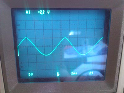
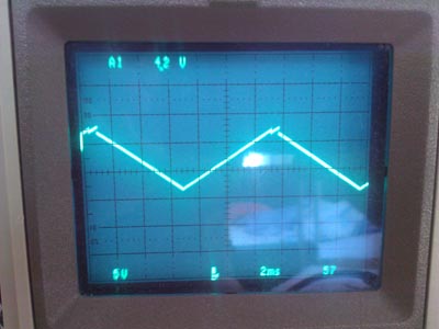
The Saw and Tri look pretty OK when the Init pot is turned left. When turned right it looks funny at the top.
The bottom half of the sine looks good. The upper half is more like a triangle.
Thank you!
| Description: |
|
| Filesize: |
44.34 KB |
| Viewed: |
38582 Time(s) |
|
| Description: |
|
| Filesize: |
38.6 KB |
| Viewed: |
38582 Time(s) |
|
|
|
|
Back to top
|
|
|
moellhoven
Joined: Jun 18, 2011
Posts: 15
Location: Germany
|
| Posted: Tue Oct 04, 2011 12:19 am Post subject:
|
|
|
| I forgot to add that I used the Bridechamber kit for 15V. |
|
|
Back to top
|
|
|
frijitz
Joined: May 04, 2007
Posts: 1734
Location: NM USA
Audio files: 54
|
| Posted: Tue Oct 04, 2011 10:09 am Post subject:
|
|
|
OK, it looks like the waveshapes are OK, just out of adjustment.
The problem with the frequency range is probably in the expo converter section: A1a, A1b and the transistor pair. There must be a wiring error or a bad component or a solder bridge or something in there somewhere.
I can't say much beyond that. If you want to measure the voltage at the A1a output (pin 1) as the coarse pot is varied from end to end, that might be helpful.
Ian |
|
|
Back to top
|
|
|
moellhoven
Joined: Jun 18, 2011
Posts: 15
Location: Germany
|
| Posted: Thu Oct 06, 2011 12:38 am Post subject:
|
|
|
Thanks for pointing me into the right direction. Will do some checking on the weekend.
There is one thing i am not sure of i got it right. The kit came with an SSM2220 but without an TempCo.
From the documentation i figured it is missing and i added one of my spares to R14b. Is this OK or is this maybe the problem? |
|
|
Back to top
|
|
|
emdot_ambient
Joined: Nov 22, 2009
Posts: 667
Location: Frederick, MD
|
| Posted: Thu Oct 06, 2011 4:49 am Post subject:
|
|
|
| moellhoven wrote: | There is one thing i am not sure of i got it right. The kit came with an SSM2220 but without an TempCo.
From the documentation i figured it is missing and i added one of my spares to R14b. Is this OK or is this maybe the problem? |
I recently built a TZFM from a Bridechamber kit (it sits untested) and they forgot the tempco on mine as well. I contacted them and they replaced it along with an apology. Apparently there was a batch of the kits where the tempcos were accidentally left out.
_________________
Looking for a certain ratio since 1978 |
|
|
Back to top
|
|
|
|

 Forum index » DIY Hardware and Software


