| Author |
Message |
brother303

Joined: Nov 02, 2010
Posts: 139
Location: ruhr-area/germany
|
|
|
Back to top
|
|
 |
Pantheon

Joined: Feb 17, 2011
Posts: 36
Location: Edinburgh
|
|
|
Back to top
|
|
|
ericcoleridge

Joined: Jan 16, 2007
Posts: 889
Location: NYC
|
 Posted: Fri Mar 18, 2011 12:47 pm Post subject: Posted: Fri Mar 18, 2011 12:47 pm Post subject:
|
  |
|
This project of yours is making me want to have other sections of the MS20 available as PCBs.
I already have both VCFs assembled and tested; they sound amazing. The PCBs I made are for the later discrete daughter board version of the MS20 LPF+HPF, which was the one I had on my MS20. The layouts are on line.
But now I think I'll try laying out the VCA, LFO, and HADSR in Layout Express. I've done a few layouts before-- unfortunately, I've yet to make one the works! But I'll give another it try. I've found nice re-draws of the VCA and LFO on Marjan Juekers site, and the HADSR on Juergen Haible's site. |
|
|
Back to top
|
|
|
brother303
Joined: Nov 02, 2010
Posts: 139
Location: ruhr-area/germany
|
| Posted: Sat Mar 19, 2011 5:42 am Post subject:
|
|
|
Hi,
| ericcoleridge wrote: | | This project of yours is making me want to have other sections of the MS20 available as PCBs. |
Exactly the same here! 
| ericcoleridge wrote: | | I already have both VCFs assembled and tested; they sound amazing. The PCBs I made are for the later discrete daughter board version of the MS20 LPF+HPF, which was the one I had on my MS20. The layouts are on line. |
I was thinking about a "kind-of-MS20-mutant" with a Polivoks-vcf and a Threeler. 
Wich layouts did you use for your vcfs?
Best regards
Greg |
|
|
Back to top
|
|
|
Pantheon
Joined: Feb 17, 2011
Posts: 36
Location: Edinburgh
|
| Posted: Sat Mar 19, 2011 4:09 pm Post subject:
|
|
|
Perhaps eventually we could group them all together in one package for a Mutant MS20 Clone. That would be pretty awesome actually.
I'd defiantly be interested in the VCA clone as I'll have to make one to match these VCO's soon. Something with a bit of character would be great. Any chance you could post a link to these redrawn schematics?
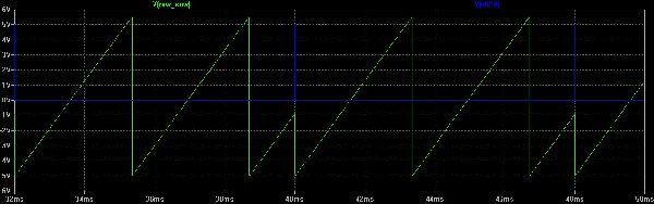
PS: the new sync appears to behave nicely this time, and sounds really great in the simulation. I'm going to mod my 1st prototype soon to try it out in the real thing.
_________________
the8bitpimp.wordpress.com |
|
|
Back to top
|
|
|
brother303
Joined: Nov 02, 2010
Posts: 139
Location: ruhr-area/germany
|
| Posted: Sat Mar 19, 2011 6:07 pm Post subject:
|
|
|
Hi,
| Pantheon wrote: | | I'd defiantly be interested in the VCA clone as I'll have to make one to match these VCO's soon. Something with a bit of character would be great. Any chance you could post a link to these redrawn schematics? |
The vca-schemos are around here on the board. Maybe ericcoleridge can give us a hint?
| Pantheon wrote: | | PS: the new sync appears to behave nicely this time, and sounds really great in the simulation. I'm going to mod my 1st prototype soon to try it out in the real thing. |
Yeah,good one!
Cheers
Greg |
|
|
Back to top
|
|
|
brother303
Joined: Nov 02, 2010
Posts: 139
Location: ruhr-area/germany
|
|
|
Back to top
|
|
|
ericcoleridge
Joined: Jan 16, 2007
Posts: 889
Location: NYC
|
|
|
Back to top
|
|
|
brother303
Joined: Nov 02, 2010
Posts: 139
Location: ruhr-area/germany
|
| Posted: Sun Mar 20, 2011 4:08 am Post subject:
|
|
|
Cool,
thank you.
Best regards
Greg |
|
|
Back to top
|
|
|
ericcoleridge
Joined: Jan 16, 2007
Posts: 889
Location: NYC
|
| Posted: Sun Mar 20, 2011 7:05 pm Post subject:
|
|
|
| I made a layout for the VCA using Marjan's drawing; I'll post it here if anyone wants to test it. Ill probably layout the LFO also, but I think the HADSR might be a little beyond my abilities. |
|
|
Back to top
|
|
|
brother303
Joined: Nov 02, 2010
Posts: 139
Location: ruhr-area/germany
|
| Posted: Mon Mar 21, 2011 4:09 am Post subject:
|
|
|
Hi,
| ericcoleridge wrote: | | I made a layout for the VCA using Marjan's drawing; I'll post it here if anyone wants to test it. Ill probably layout the LFO also... |
Good one! I´d like to test the vca-layout, 
VCO/VCF/VCA are the most important components to build imho. A kind if "barebone"-MS20...
I built something similar with ARP-stuff some times ago.
Odyssey dual-vco/ringmod,a 4023-12db,a 4035-24db and the vca from an ARP2600.
I only added one audio mixer and put the whole stuff behind a 42hp eurorack-panel.
Best regards
Greg |
|
|
Back to top
|
|
|
brother303
Joined: Nov 02, 2010
Posts: 139
Location: ruhr-area/germany
|
|
|
Back to top
|
|
|
Pantheon
Joined: Feb 17, 2011
Posts: 36
Location: Edinburgh
|
|
|
Back to top
|
|
|
ericcoleridge
Joined: Jan 16, 2007
Posts: 889
Location: NYC
|
| Posted: Mon Mar 21, 2011 1:59 pm Post subject:
|
|
|
This is probably not the best place to post these, but, being that they are related, I'll go ahead for now.
These are layouts for the MS20 VCA and LFO, both untested as of 3/21/11. I was pretty careful laying out the VCA, less so with the LFO; But both are very simple and if anythings wrong, shouldn't take much to get them working. The VCA calls for matched BC549s, but I don't know how critical this is.
I used a freeware program called DIY Layout Creator, which is a little buggy. The layouts will need to be re-sized before printing to PnP, and I think they may also need to be reversed.
| Description: |
|
| Filesize: |
20.27 KB |
| Viewed: |
1049 Time(s) |
| This image has been reduced to fit the page. Click on it to enlarge. |
|
| Description: |
|
| Filesize: |
7.03 KB |
| Viewed: |
470 Time(s) |
| This image has been reduced to fit the page. Click on it to enlarge. |
|
| Description: |
|
| Filesize: |
14.53 KB |
| Viewed: |
2324 Time(s) |
| This image has been reduced to fit the page. Click on it to enlarge. |
|
| Description: |
|
| Filesize: |
5.9 KB |
| Viewed: |
481 Time(s) |
| This image has been reduced to fit the page. Click on it to enlarge. |
|
|
|
|
Back to top
|
|
|
brother303
Joined: Nov 02, 2010
Posts: 139
Location: ruhr-area/germany
|
| Posted: Tue Mar 22, 2011 6:50 am Post subject:
|
|
|
Hi,
| ericcoleridge wrote: | | This is probably not the best place to post these, but, being that they are related, I'll go ahead for now. |
Thanks lot for posting this here. 
The vca looks easy enough,I´ll try to put it on a piece of stripboard.
Best regards
Greg |
|
|
Back to top
|
|
|
brother303
Joined: Nov 02, 2010
Posts: 139
Location: ruhr-area/germany
|
| Posted: Tue Mar 22, 2011 9:58 am Post subject:
|
|
|
Hi,
@Pantheon: How many ins and outs does your vco provide? Exactly like the "real thing"?
Outs : Tri, saw, square
Ins : V/oct., pwm, freq.1, freq.2
And another question : Is there a coarse and a fine tune pot or an octave switch and a tune pot?
Thanks!
Cheers
Greg |
|
|
Back to top
|
|
|
Pantheon
Joined: Feb 17, 2011
Posts: 36
Location: Edinburgh
|
| Posted: Tue Mar 22, 2011 12:16 pm Post subject:
|
|
|
It has 5 inputs:
2x - 1/voct inputs
1x - sync input
1x - linear cv
1x - pwm input
1 of the 1/voct should come out to the faceplate, or be routed internaly to a MidiCV converter, etc.
The other one is for the Fine/Course tuning pot. I havent decided exactly how im going to use this yet. Currently im hovering over the idea of octave/finetune. I'll include a diagram of how I wire it, but people should be able to use this to suit themselves I think.
The sync input can connect to the square/pulse wave of any oscillator (at +5v/-5v), and will sync on the rising edge of that wave.
The linear cv is of no use to me but it seems to be a standard thing to include in VCO's so I put one in. Also Sebo might be able to use it to get this oscillator to track from a v/Hertz cv.
The PWM input takes a CV of [0v - 5v] and sets a [50% - 0%] duty cycle, respectively. The PWM cv could also range to -5v to get >50% duty cycle.
I am going to wire a pot as an attenuator feeding into this, and depending on if a jack is plugged into the CV input or not, it will either set PWM directly or attenuate a signal coming in threw the jack.
I has 5 outputs:
1x - Saw wave
1x - Triangle wave
3x - Pulse wave
There are three pulse outputs, so that one can be internaly routed to a second oscillator to allow syncing. One can also be internally routed to a CMOS ring modulator.
Does that seem reasonable?
These features suit me, but feel free to make suggestions, I can still change the board.
Also I have finished routing the new board, so after a double check, i'll etch and test it 
_________________
the8bitpimp.wordpress.com |
|
|
Back to top
|
|
|
brother303
Joined: Nov 02, 2010
Posts: 139
Location: ruhr-area/germany
|
| Posted: Wed Mar 23, 2011 4:41 am Post subject:
|
|
|
Hi,
| Pantheon wrote: | | It has 5 inputs |
| Pantheon wrote: | | It has 5 outputs |

| Pantheon wrote: | | The other one is for the Fine/Course tuning pot. I havent decided exactly how im going to use this yet. Currently im hovering over the idea of octave/finetune. I'll include a diagram of how I wire it, but people should be able to use this to suit themselves I think. |
A rotary switch for selecting the octaves with a range from -2 to +3 or -1 to +4 is what I like best.
Something like this :
http://www.elby-designs.com/synth-modules/octave/octave.htm
| Pantheon wrote: | | The sync input can connect to the square/pulse wave of any oscillator (at +5v/-5v), and will sync on the rising edge of that wave. |
Cool. Since there are 3 square outs,I´ll put one of them on a switch connected to sync in for internal sync.
| Pantheon wrote: | | The linear cv is of no use to me but it seems to be a standard thing to include in VCO's so I put one in. |
I think,this input is absolutely important to play around with synced or ringmodulated vcos! Hook up an lfo to this input while using the ringmod is fun!
| Pantheon wrote: | | I am going to wire a pot as an attenuator feeding into this, and depending on if a jack is plugged into the CV input or not, it will either set PWM directly or attenuate a signal coming in threw the jack. |
Just as on the original,perfect.
| Pantheon wrote: | | Does that seem reasonable? |
Absolutely! 
| Pantheon wrote: | | Also I have finished routing the new board, so after a double check, i'll etch and test it |

Cheers
Greg |
|
|
Back to top
|
|
|
brother303
Joined: Nov 02, 2010
Posts: 139
Location: ruhr-area/germany
|
|
|
Back to top
|
|
|
Pantheon
Joined: Feb 17, 2011
Posts: 36
Location: Edinburgh
|
| Posted: Wed Mar 23, 2011 11:03 am Post subject:
|
|
|
Hey 303,
Thoes are some great links you have there. I have been testing the VCA myself in spice and it seems to function fairly nicely. I made a few tweaks to it that I will share if anyone is interested.
As for the Octave/Finetune switch, im in two minds about what to do with it.
As with the link you provided, I need to use a dual opamp for a buffer, these buffers then feed into the 1v/oct inputs. But I cant decide where to place this little circuit. I would be most happy i think, putting it on a little board of its own. This way, everything is as flexible as it can be, people can pick and choose what they want. The only problem is its a little bit more of a pain to etch/wire everything up, but not much.
If I do choose this route, i'll probably make it pot-mounted so that its less of a hassle. Then you can wire it to both the rotory switch, and the vco board.
So my plan for this mini board is:
4x Inputs:
+12v, -12v, gnd, +5v
these all come from the vco board.
1x Mounted Pot:
this is as a fine tune control, and typicaly covers an entire octave in a full sweep, left to right.
1x Non Mounted Rotary Switch:
This can have up to five steps, each of which represents one octave.
1x Output:
This is the sum of both the pot and the rotary switch, and wires directly into the 1v/oct input on the vco board.
Does that seem like a good plan? I have tested that circuit, and im sure it will work.
I have also made a layout for a small board with the ring modulator on it.
_________________
the8bitpimp.wordpress.com |
|
|
Back to top
|
|
|
brother303
Joined: Nov 02, 2010
Posts: 139
Location: ruhr-area/germany
|
| Posted: Thu Mar 24, 2011 3:49 am Post subject:
|
|
|
Hi,
| Pantheon wrote: | | I have been testing the VCA myself in spice and it seems to function fairly nicely. I made a few tweaks to it that I will share if anyone is interested. |
Good to hear the circuit is working. I´m going to put two of them on a small piece of stripboard. What tweaks did you make?
| Pantheon wrote: | So my plan for this mini board is:
4x Inputs:
+12v, -12v, gnd, +5v
these all come from the vco board.
1x Mounted Pot:
this is as a fine tune control, and typicaly covers an entire octave in a full sweep, left to right.
1x Non Mounted Rotary Switch:
This can have up to five steps, each of which represents one octave.
1x Output:
This is the sum of both the pot and the rotary switch, and wires directly into the 1v/oct input on the vco board. |
That`s exactly what I had in mind. Go ahead...
| Pantheon wrote: | | I have also made a layout for a small board with the ring modulator on it. |
Why not putting the ringmod directly on the vco-pcb? It´s only a small circuit with a very few parts.
I thinks,when it´s all done,we´ll get a real beasty of an MS-mutant-20...
Cheers
Greg |
|
|
Back to top
|
|
|
Pantheon
Joined: Feb 17, 2011
Posts: 36
Location: Edinburgh
|
| Posted: Thu Mar 24, 2011 4:03 pm Post subject:
|
|
|
I have attached the version of the ms20 vca that I simulated. There are a couple of notes on there, for setting line level and synth level outputs. I also added a gain trim pot, as the verson you linked to seemed to output a slightly lower signal level. Also I removed the bias trim, as I couldnt see much reason for it in the circuit. Does anyone know why it was included?
As for the question of puting the ring mod on the vco board, as it stands the vco is realy nicely layed out and everything fits great. If I were to put it on the board, it would either become a very long board, or become a routing nightmare. I quite like the fact that its a very small vco board right now (4.30"x1.50"). The ring mod board is (2"x1") on its own. The ring mod, could have 3 sockets mounted on it, and just attach directly to the face plate, no problem. You could then also use it with other modules.
Im about to finaly sit down and check the vco to make sure its routed correctly. I got a little sidetracked with some tube circuits 
| Description: |
|

Download (listen) |
| Filename: |
MS20VCA.pdf |
| Filesize: |
11.81 KB |
| Downloaded: |
779 Time(s) |
_________________
the8bitpimp.wordpress.com |
|
|
Back to top
|
|
|
brother303
Joined: Nov 02, 2010
Posts: 139
Location: ruhr-area/germany
|
| Posted: Fri Mar 25, 2011 12:46 pm Post subject:
|
|
|
Hi,
| Pantheon wrote: | | I have attached the version of the ms20 vca that I simulated... |
Thanks mate. I´m going to check it on a stripboard over the weekend. (....thank god it`s friday! )
| Pantheon wrote: | | As for the question of puting the ring mod on the vco board, as it stands the vco is realy nicely layed out and everything fits great. |
No problem here,just an idea. Pcb size is good as it is and...
| Pantheon wrote: | | ...the ring mod could have 3 sockets mounted on it, and just attach directly to the face plate, no problem. |
| Pantheon wrote: | | Im about to finaly sit down and check the vco to make sure its routed correctly. |
Can`t wait to etch some boards and put this stuff together.
The "M"utant "S"ynth 20 is coming! 
| Pantheon wrote: | | I got a little sidetracked with some tube circuits |
And I am a little sidetracked with a Klee-sequencer!
Cheers
Greg |
|
|
Back to top
|
|
|
brother303
Joined: Nov 02, 2010
Posts: 139
Location: ruhr-area/germany
|
| Posted: Sat Mar 26, 2011 11:44 am Post subject:
|
|
|
Hi Pantheon,
R12 on your vca-schematics is really 1000K?!? 
Not 10K???
Cheers
Greg |
|
|
Back to top
|
|
|
Pantheon
Joined: Feb 17, 2011
Posts: 36
Location: Edinburgh
|
| Posted: Sat Mar 26, 2011 1:32 pm Post subject:
|
|
|
| brother303 wrote: | Hi Pantheon,
R12 on your vca-schematics is really 1000K?!?
Not 10K???
Cheers
Greg |
Ah yes its a 1M resistor, but it realy isnt that important, 47k or something might be more resonable It was just to tie that end of the cap to ground.
I hope it works for you, let us know your results!
I finished checking my board layout, and after a couple of tweaks everything looks good and checks out ok So when the printers are open on monday, i'll get this printed and etched. Once i'm happy that its working correctly, i'll post up the final layout, schematic, parts placement, etc.
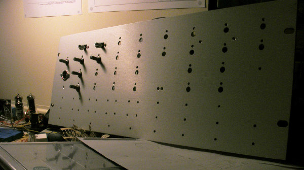
I also started machining a front pannel for this MutantMS20 clone (a partial clone realy), it should all fit on a 4U 19" Rack pannel, there is a pic of the partialy machined front pannel attached. Sorry for the crap quality, my camera is lame in dim light.
Does anyone have any good tips on how to apply text to a face plate?
I have tought about toner transfering it on, then sealing it with some spray. My dad suggested silk screening, but I dont have any idea how its actualy done.
| Description: |
| Partialy Machined Faceplate |
|
| Filesize: |
506.89 KB |
| Viewed: |
344 Time(s) |
| This image has been reduced to fit the page. Click on it to enlarge. |
|
_________________
the8bitpimp.wordpress.com |
|
|
Back to top
|
|
|
|

 Forum index » DIY Hardware and Software » Developers' Corner