| Author |
Message |
emdot_ambient
Joined: Nov 22, 2009
Posts: 667
Location: Frederick, MD
|
|
|
Back to top
|
|
 |
Skrog Productions

Joined: Jan 07, 2009
Posts: 1215
Location: Scottish Borders
Audio files: 158
|
|
|
Back to top
|
|
|
Skrog Productions
Joined: Jan 07, 2009
Posts: 1215
Location: Scottish Borders
Audio files: 158
|
 Posted: Fri Jul 22, 2011 11:56 am Post subject: Posted: Fri Jul 22, 2011 11:56 am Post subject:
|
  |
|
here are some sounds using the arpeggiator with my modular.
first mp3 is the arp with keyboard cv to transpose while i turn the rotary switches.
Second mp3 is my mfos 16 step sequencer cv controlling the note sets while being clocked 8 times slower than the arpeggiator speed ( all clocked from Fonik Clock ) .
The arp cv & Gate outs are patched up to a simple 2 vco monosynth config. on the modular.
Dave.
| Description: |
|

Download (listen) |
| Filename: |
arpeggiator test 1.mp3 |
| Filesize: |
5.63 MB |
| Downloaded: |
1114 Time(s) |
| Description: |
|
Download (listen) |
| Filename: |
seq to note set cv arpeggiator test.mp3 |
| Filesize: |
2.16 MB |
| Downloaded: |
1135 Time(s) |
|
|
|
Back to top
|
|
|
brother303

Joined: Nov 02, 2010
Posts: 139
Location: ruhr-area/germany
|
| Posted: Sat Jul 23, 2011 3:25 am Post subject:
|
|
|
Hi Dave,
| Skrog Productions wrote: | | Here are the resistor choices i made... |
Thanks,that´s exactly what I need. Cool!
| Skrog Productions wrote: | Remember , you may want just the Rate (Tempo) pot which doubles as the divider control when you plug a jack into the ext clock 3-pole socket , i finished my panel before i read this  , when i want internal clock tempo i use the rate pot , when i want external clock division i flick a switch to use the rotary instead of the rate pot. , when i want internal clock tempo i use the rate pot , when i want external clock division i flick a switch to use the rotary instead of the rate pot. |
Good idea,I´ll keep it in mind when building this unit.

THX!
_________________
Best regards
Greg |
|
|
Back to top
|
|
|
LektroiD

Joined: Aug 23, 2008
Posts: 1019
Location: Scottish Borders
Audio files: 2
G2 patch files: 2
|
| Posted: Thu Mar 01, 2012 10:00 pm Post subject:
|
|
|
I've just built this Arpeggiator as "the works" (example 3), but the build docs don't actually indicate what each control or socket does, only where to wire it to the PCB. (I'd really like to see round the front of the example to see what's going on)...
I'm just plugging stuff in and out but not really knowing what is going on with it since nothing is labelled properly.. the socket connected to XCLK and CKEN (I'm presuming it is a clock of some description), is that an in or an out? I connected it to an external clock and it does some weird rhythms, like it is taking the rhythm from both internal and external at the same time, is this normal?
There's also 3 CV in sockets and 4 controls connected to various CV connections on the board. Turning the dials has different effects for each, but I have no idea what they are really doing.
Also, the 3rd & 7th sockets, are these outputs? Do I need to connect these and the main CV out to a CV mixer to make them work?
If anyone knows what the labelling should be on "the works" (3rd example in build docs), please let me know, I'm scratching my head here.  |
|
|
Back to top
|
|
|
Skrog Productions
Joined: Jan 07, 2009
Posts: 1215
Location: Scottish Borders
Audio files: 158
|
| Posted: Sun Mar 04, 2012 9:49 am Post subject:
|
|
|
Hi Rich , how are you .
The 3rd & 7ths sockets are inputs , i think it's a sort of digital input to switch between Major and minor , high / low switching.
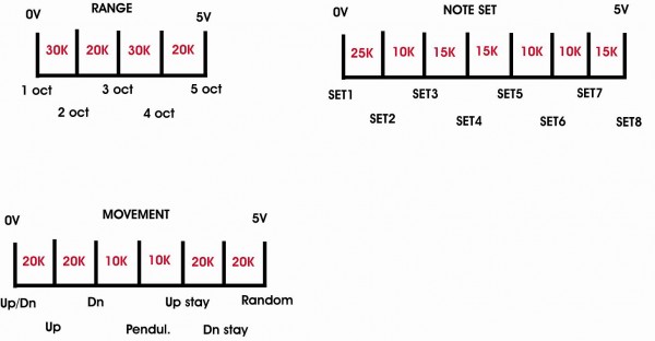
The control dials.... have a look at my rotary diagram up above , they represent a flattened out pot track , the resistor joins are roughly where the range / movement / note set would change function if you are using pots only turning the dial .
The internal clock for stand alone mode is wired to a stereo panel jack wired up for internal clock (no jack plugged in) or external clock (jack in & disabling internal clock , when that is done the internal rate pot now acts as a variable divider for the external clock pulse .
I remember i had a bit of head scratching planning this one out , but its great once you understand it , it really thickens out my sequency music i do , great pcb & pic 
Dave |
|
|
Back to top
|
|
|
ericcoleridge

Joined: Jan 16, 2007
Posts: 889
Location: NYC
|
| Posted: Sun Mar 04, 2012 10:55 am Post subject:
|
|
|
| Skrog Productions wrote: |
Fantastic module , im having great fun with this & i got some ideas for a new track
|
Nice build. When this was offered, I was trying to think of a way that some of the switches could possibly be controlled by a little octave or octave+half keyboard (not sure where I would even get such a keyboard). It just seemed like too many switches to control all at once for any kind of practical real-time performance.
Your recording sounds really good and demonstrates that this modules can be 'played'. I'd love to see a video as well, if you ever get a chance. |
|
|
Back to top
|
|
|
LektroiD
Joined: Aug 23, 2008
Posts: 1019
Location: Scottish Borders
Audio files: 2
G2 patch files: 2
|
| Posted: Sun Mar 04, 2012 10:53 pm Post subject:
|
|
|
| Skrog Productions wrote: | Hi Rich , how are you .
The 3rd & 7ths sockets are inputs , i think it's a sort of digital input to switch between Major and minor , high / low switching. |
Hi Dave, many thanks for this.
Is this like a gate signal, or should I send something else? I tried a few different things going in and out, but nothing seems to do anything significant.
| Quote: | | The control dials.... have a look at my rotary diagram up above , they represent a flattened out pot track , the resistor joins are roughly where the range / movement / note set would change function if you are using pots only turning the dial . |
I'm not really clear on which pots are doing what just now.. I'll keep playing with it and see if I can work it out.. I wish the docs were clearer.
| Quote: | | The internal clock for stand alone mode is wired to a stereo panel jack wired up for internal clock (no jack plugged in) or external clock (jack in & disabling internal clock , when that is done the internal rate pot now acts as a variable divider for the external clock pulse . |
I've definitely got the clock thing wired up wrong with what it's doing. It's really hard to tell what's going on with the type of sockets depicted in the diagram.
| Quote: | I remember i had a bit of head scratching planning this one out , but its great once you understand it , it really thickens out my sequency music i do , great pcb & pic
Dave |
Thanks again, I'll persevere. Hopefully I'll work it out and not blow the thing up...   |
|
|
Back to top
|
|
|
LektroiD
Joined: Aug 23, 2008
Posts: 1019
Location: Scottish Borders
Audio files: 2
G2 patch files: 2
|
| Posted: Mon Mar 05, 2012 12:31 pm Post subject:
|
|
|
Hmmm, just a quick one, the pot attached to CV1 which seems to control Pulse Width also changes the pitch by a semitone or more... Is that a feature or a bug?
Also, what is AUX IN? Auxiliary what? CV? Audio?... I put a voltage in from an LFO and wound up the dial, it shut down... |
|
|
Back to top
|
|
|
aladan
Joined: Aug 13, 2011
Posts: 52
Location: Australia
|
Posted: Fri Mar 09, 2012 5:48 pm Post subject:
Subject description: My BMC-003 build experience... |
|
|
I built my BMC-003 last night (first of two) and here is my experience.
* Spend time reading the build doc and understanding it before you start *
You need to understand this module before you build it. It is quite customisable, with some unconnected 'building blocks' (AUX, CVIN1, CVIN2) and numerous panel options that you can mold to your personal needs/wants. But if you just jump in without reading the docs, you will most likely get confused.
Pros: it works as described, is fun to use and is quite flexible in design. The board quality is good, double-sided, and the integrated +5V supply circuitry is a handy feature. Mine worked first time (once I corrected the power supply pins which I had wired backwards the first time round - doh!)
Cons: Please note that these are very minor criticisms! The renumbering of the PIC pins in the middle of the instructions (to cater for the 8+14 pin socket hack) can be a little confusing. The resistor pads are pretty close together - I had to bend the resistor pins quite close to the ends.
I am running on a 4MHz crystal because I didn't have a 20MHz handy.
Summary: great module, flexible but read the instructions thoroughly first!
Thank you Michael! |
|
|
Back to top
|
|
|
baudrate

Joined: Mar 19, 2012
Posts: 27
Location: Utah
|
| Posted: Wed May 02, 2012 12:57 pm Post subject:
|
|
|
Does anyone know if these boards (well any Barton PCB's) are still available? I've been trying to get in touch with Michael for about 6 weeks now with no luck. I know a few people on Muffwigglers are in the same boat.  |
|
|
Back to top
|
|
|
haxster
Joined: Feb 01, 2006
Posts: 246
Location: MONTEREY PARK, CA 91754
G2 patch files: 2
|
| Posted: Thu May 03, 2012 10:06 am Post subject:
|
|
|
| I really hope he is okay, I will try to email him too. I was buying large packs of Arp CV pics from him. |
|
|
Back to top
|
|
|
|

 Forum index » DIY Hardware and Software