| Author |
Message |
PHOBoS

Joined: Jan 14, 2010
Posts: 5881
Location: Moon Base
Audio files: 709
|
|
|
Back to top
|
|
 |
DES

Joined: Feb 28, 2003
Posts: 796
Location: New Jersey
Audio files: 8
|
 Posted: Sun Jan 17, 2016 12:13 pm Post subject: Posted: Sun Jan 17, 2016 12:13 pm Post subject:
|
  |
|
Nice clean build. 🙂. Looking forward to the rest.
_________________
Dave
www.davesneed.com |
|
|
Back to top
|
|
|
PHOBoS
Joined: Jan 14, 2010
Posts: 5881
Location: Moon Base
Audio files: 709
|
Posted: Sun Jan 31, 2016 4:07 pm Post subject:
Melt Yer Face
Subject description: Multi/Interface module |
|
|
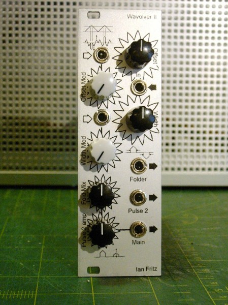
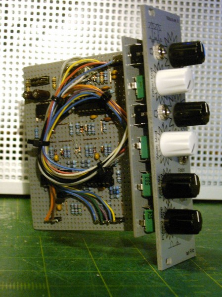
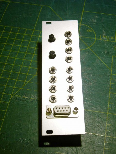
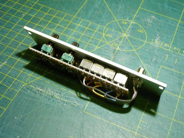
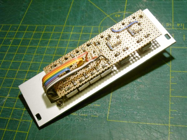
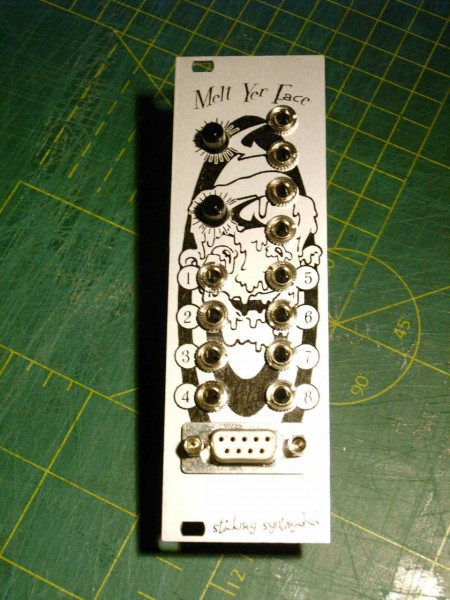
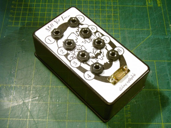
All my other synths use 1/4" jacks so I need something to convert those to 1/8". My initial idea was a panel
with both 1/4" and 1/8" sockets but you can't get a lot of 1/4" on a panel. So instead I made a panel
with 8x 1/8" sockets connected to a 9P sub-D connector. This will plug into a breakout box with 1/4" sockets
which, as an added bonus, I can put next to my synths. when nothing is plugged in on the other side it
also acts as a multiple. It can also be used as a multiple when something is plugged in but than I have to
leave a minimum of 2 sockets unused. Since there was some panel space left I also added 2 attenuators.
| Description: |
|
| Filesize: |
96.06 KB |
| Viewed: |
807 Time(s) |
| This image has been reduced to fit the page. Click on it to enlarge. |
|
| Description: |
|
| Filesize: |
123.14 KB |
| Viewed: |
809 Time(s) |
| This image has been reduced to fit the page. Click on it to enlarge. |
|
| Description: |
|
| Filesize: |
127 KB |
| Viewed: |
804 Time(s) |
| This image has been reduced to fit the page. Click on it to enlarge. |

|
| Description: |
|
| Filesize: |
123.92 KB |
| Viewed: |
850 Time(s) |
| This image has been reduced to fit the page. Click on it to enlarge. |
|
| Description: |
|
| Filesize: |
59.71 KB |
| Viewed: |
849 Time(s) |
| This image has been reduced to fit the page. Click on it to enlarge. |
|
_________________
"My perf, it's full of holes!"
http://phobos.000space.com/
SoundCloud BandCamp MixCloud Stickney Synthyards Captain Collider Twitch YouTube |
|
|
Back to top
|
|
|
PHOBoS
Joined: Jan 14, 2010
Posts: 5881
Location: Moon Base
Audio files: 709
|
| Posted: Fri Feb 19, 2016 2:17 pm Post subject:
toner transfer front panels |
|
|
I had seen some people having nice results with the toner transfer method to make front panels so I gave that a try myself.
I first tried it with some regular paper but that didn't work very well. So next I tried some pages from a couple of different
magazines. I got much better results but the toner didn't take 100% and I also got some of the print of the magazines itself
on it. But what was transferred looked good and was pretty scratch proof.
So I ordered some photopaper to see if that would work any better. What I only relalized after I got it was that it was
made for inktjet printers. It didn't say that it wasn't suitable for laserprinters though so gave it a try anyway.
Well,.. when it came out of my printer it sounded like unwrapping some candy  The print had cracks in it and the The print had cracks in it and the
paper had become all bubbly. So that did NOT work. I looked for a bit more info and actually came across some warnings
against using glossy inktjet paper in a laser printer. Apparently the glossy coating can melt and stick to the fuser,
ruining the printer. Luckely that didn't seem to have happened. However there are people who are getting great results
with it even using the exact paper I tried. So you could try it but be warned!
I read up some more about toner transfer method and somewhere someone mentioned getting great results using cheap transfer
paper from china available on ebay. So I ordered some of that (pretty cheap indeed and no shipping costs!). That was all
about a month ago and I had almost given up on receiving the paper when it arrived yesterday 
So I could get back to testing. It came out of my printer looking great, but while cutting it to size I did notice that the
toner didn't stick very well to it. Of course that's exactly what you need to make good transfers but you also have to be
very careful when handeling it. The first tranfer I made looked horrible and much worse than the ones I had made using the
magazine paper.  So I gave it another try. Sofar I had been emerging the (very HOT!) aluminium in water after the transfer So I gave it another try. Sofar I had been emerging the (very HOT!) aluminium in water after the transfer
to rub of the paper. But the scrap piece I was testing on didn't really fit in my sink so only a small part got emerged this
time. Now, when I pulled of the paper (you don't have to rub this transfer paper of) the part that was emerged looked bad
again but the part that wasn't looked great  So on the next try I just let it cool of by itself and that seem to do the trick. So on the next try I just let it cool of by itself and that seem to do the trick.
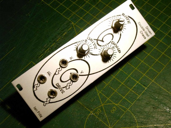
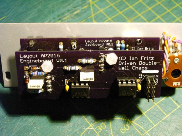
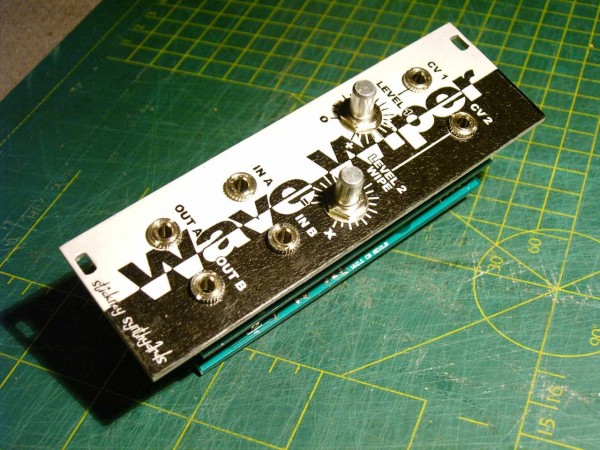
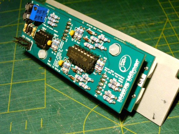
I made 4 panels sofar. the 'Melt Yer face', EZChaos for which I got the PCBs from AlanP and two WaveWipers. I had some trouble
getting the large black area of the WaveWiper panels to tranfer 100% but after a couple of tries it worked. Here are some photos.
| Description: |
|
| Filesize: |
118.8 KB |
| Viewed: |
843 Time(s) |
| This image has been reduced to fit the page. Click on it to enlarge. |
|
| Description: |
| EZ Chaos / Driven Double-Well Chaos |
|
| Filesize: |
105.16 KB |
| Viewed: |
809 Time(s) |
| This image has been reduced to fit the page. Click on it to enlarge. |
|
| Description: |
| EZ Chaos / Driven Double-Well Chaos |
|
| Filesize: |
117.98 KB |
| Viewed: |
868 Time(s) |
| This image has been reduced to fit the page. Click on it to enlarge. |
|
| Description: |
|
| Filesize: |
143.86 KB |
| Viewed: |
817 Time(s) |
| This image has been reduced to fit the page. Click on it to enlarge. |
|
| Description: |
|
| Filesize: |
125.64 KB |
| Viewed: |
805 Time(s) |
| This image has been reduced to fit the page. Click on it to enlarge. |
|
_________________
"My perf, it's full of holes!"
http://phobos.000space.com/
SoundCloud BandCamp MixCloud Stickney Synthyards Captain Collider Twitch YouTube |
|
|
Back to top
|
|
|
L´Andratté

Joined: Sep 23, 2012
Posts: 151
Location: Hamburg, Germany
Audio files: 5
|
| Posted: Fri Feb 19, 2016 4:35 pm Post subject:
|
|
|
  |
|
|
Back to top
|
|
|
cyclic

Joined: Mar 15, 2015
Posts: 95
Location: hobart
|
| Posted: Mon Feb 22, 2016 10:52 pm Post subject:
Re: toner transfer front panels |
|
|
| PHOBoS wrote: | I had seen some people having nice results with the toner transfer method to make front panels so I gave that a try myself.
I first tried it with some regular paper but that didn't work very well. So next I tried some pages from a couple of different
magazines. I got much better results but the toner didn't take 100% and I also got some of the print of the magazines itself
on it. But what was transferred looked good and was pretty scratch proof.
So I ordered some photopaper to see if that would work any better. What I only relalized after I got it was that it was
made for inktjet printers. It didn't say that it wasn't suitable for laserprinters though so gave it a try anyway.
Well,.. when it came out of my printer it sounded like unwrapping some candy The print had cracks in it and the
paper had become all bubbly. So that did NOT work. I looked for a bit more info and actually came across some warnings
against using glossy inktjet paper in a laser printer. Apparently the glossy coating can melt and stick to the fuser,
ruining the printer. Luckely that didn't seem to have happened. However there are people who are getting great results
with it even using the exact paper I tried. So you could try it but be warned!
I read up some more about toner transfer method and somewhere someone mentioned getting great results using cheap transfer
paper from china available on ebay. So I ordered some of that (pretty cheap indeed and no shipping costs!). That was all
about a month ago and I had almost given up on receiving the paper when it arrived yesterday
|
hey,
you've reminded me that I keep meaning to post this somewhere:
I have excellent toner transfers using the backing paper from sticker sheets. We use these at work for patient labels and when I'm done I just pull off all the unused stickers and use the shiny backing paper.
It seems kind of wasteful to chuck out the actual product, but this is healthcare, and often they print out a whole sheet, use one sticker and then shred the rest anyway...
I can't understand why no-one else has mentioned this anywhere before!
(and sorry that my mention here means its likely to get lost in an obscure corner...)
Anyway, It takes the image from the laserjet perfectly, then it transfers very nicely with half a dozen runs through the laminator and then the sheet JUST FALLS OFF. I actually think that if the sheet were taped onto the PCB it would actually just fall off after 2 or three passes of the laminator.
There is NO 'rubbing under water'
There is NO 'transfer of the original image.
For me personally, the failures have been from the density of the ink itself and the slowness of etching I've done with muriatic acid + peroxide. So I've just ordered some pulsar foils to remedy the first problem and am going ot heat up the etchant next time for the second.
Also, since I'm using work printers too, I have no control over 'get a new cartridge,' but I do know that the printer at my old site was better than the identical one at my new site. Go figure.... Sometimes if the artwork doesn't have any tiny traces I do two overlays to double up the ink, but hopefully the pulsar foils will mean I don;t have to do that anymore.
So, I'm not saying I have excellent home made PCBs, but I think that I DO have excellent success on the ACTUAL TONER TRANSFER steps of the process.
I just went out and checked the brand of our sticker sheets, and it looks like they are more or less no-name brand (after all, this is public health care here!) so I assume that any brand should give similar results.
Just for completeness, curerntly I am using sheets with about 10 small stickers all in one big block, and then a whole bunch of smaller ones up above it, but we have previously had sheets which have probably 14 stickers in two columns instead.
I'm planning on doing some in the next week or so, so if anyone cares, pipe up and I'll take some photos along the way...
cheers
Lance |
|
|
Back to top
|
|
|
PHOBoS
Joined: Jan 14, 2010
Posts: 5881
Location: Moon Base
Audio files: 709
|
| Posted: Tue Feb 23, 2016 3:27 am Post subject:
Re: toner transfer front panels |
|
|
| EL BO wrote: | | I have excellent toner transfers using the backing paper from sticker sheets. We use these at work for patient labels and when I'm done I just pull off all the unused stickers and use the shiny backing paper. |
I am not surprised since that is exacly what the transfer paper looks/feels like One of the videos I came across
while looking for more info on it actually mentioned using the backing paper of self-adhesive labels. So yeah if you have
easy access to it, it is perfect.
Oh and I thought about using a laminator but it would have to be able to take 2mm panels, and it would also need
a lot more heat than a PCB which only has a very thin layer of copper. If I would stumble upon a cheap one at
a thriftstore I might give it a try, but I have no way of knowing beforehand if one would be suitable and it might even
break in he process. So for now I just use an iron.
_________________
"My perf, it's full of holes!"
http://phobos.000space.com/
SoundCloud BandCamp MixCloud Stickney Synthyards Captain Collider Twitch YouTube |
|
|
Back to top
|
|
|
solaneu
Joined: Oct 21, 2014
Posts: 5
Location: suburban base
|
| Posted: Wed Mar 09, 2016 3:34 pm Post subject:
|
|
|
| Hi PHOBoS, I have a question. Looking at your MeltYerFace module, I see you mounted jacks with solder lugs on a perfboard. They seem intact so how did you manage to squeeze them through those holes? |
|
|
Back to top
|
|
|
PHOBoS
Joined: Jan 14, 2010
Posts: 5881
Location: Moon Base
Audio files: 709
|
|
|
Back to top
|
|
|
PHOBoS
Joined: Jan 14, 2010
Posts: 5881
Location: Moon Base
Audio files: 709
|
| Posted: Fri Apr 08, 2016 4:29 pm Post subject:
Melt Yer Face breakout box |
|
|
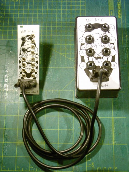
I finally got some sockets to built the Melt Yer Face breakout box
| Description: |
|
| Filesize: |
213.63 KB |
| Viewed: |
599 Time(s) |
| This image has been reduced to fit the page. Click on it to enlarge. |
|
| Description: |
|
| Filesize: |
223.45 KB |
| Viewed: |
594 Time(s) |
| This image has been reduced to fit the page. Click on it to enlarge. |
|
_________________
"My perf, it's full of holes!"
http://phobos.000space.com/
SoundCloud BandCamp MixCloud Stickney Synthyards Captain Collider Twitch YouTube |
|
|
Back to top
|
|
|
PHOBoS
Joined: Jan 14, 2010
Posts: 5881
Location: Moon Base
Audio files: 709
|
| Posted: Sun Apr 10, 2016 1:29 pm Post subject:
Moth Mixer module |
|
|
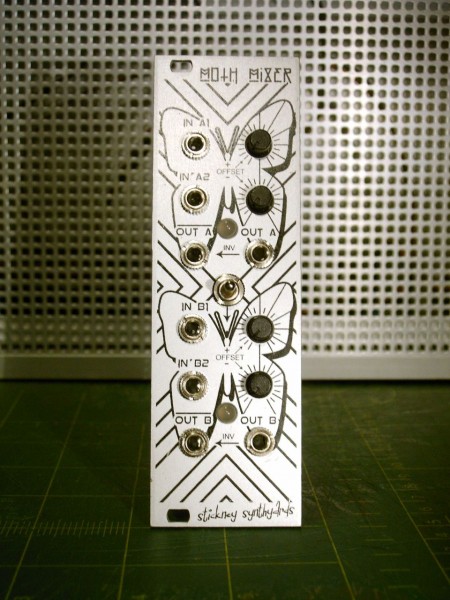
I also got some pots so I can finish some modules. Here is the first one, the Moth Mixer. (yes those are butterflies on the panel)
I wanted a simple mixer but I added some extra features. With the resistors wired to the switch contacts of the input sockets an offset
voltage can be added when nothing is plugged in, +10V with the pots connected to A1/B1 and -10V with the pots connected to A2/B2.
Besides using it as an offset control it could also be used to create a DC voltage. Both mixers have an inverted output and there is a
switch to link one of the outputs of mixer A to mixer B creating a 4 input mixer. I also added some indicators that light up if the output
voltage is lower than -5V (red) or higher than +5V (green).
I made one mistake. When I drew the PCB layout I somehow labeled the 130K resistors as 360K so that's also what I
soldered on the PCB. They are located in a spot where I couldn't replace them but I managed to solder some resistors in
parallel to bring them down to the correct value.
| Description: |
|
| Filesize: |
35.4 KB |
| Viewed: |
668 Time(s) |
| This image has been reduced to fit the page. Click on it to enlarge. |
|
| Description: |
|
| Filesize: |
200.23 KB |
| Viewed: |
611 Time(s) |
| This image has been reduced to fit the page. Click on it to enlarge. |
|
| Description: |
|
| Filesize: |
227.75 KB |
| Viewed: |
565 Time(s) |
| This image has been reduced to fit the page. Click on it to enlarge. |
|
| Description: |
|
| Filesize: |
159.57 KB |
| Viewed: |
573 Time(s) |
| This image has been reduced to fit the page. Click on it to enlarge. |

|
_________________
"My perf, it's full of holes!"
http://phobos.000space.com/
SoundCloud BandCamp MixCloud Stickney Synthyards Captain Collider Twitch YouTube |
|
|
Back to top
|
|
|
PHOBoS
Joined: Jan 14, 2010
Posts: 5881
Location: Moon Base
Audio files: 709
|
| Posted: Sun Apr 10, 2016 4:48 pm Post subject:
|
|
|
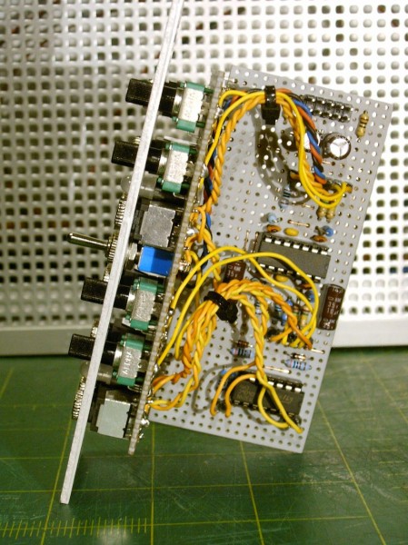
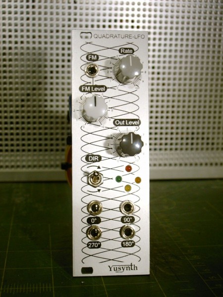
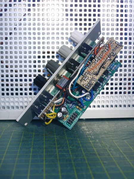
And another one finished: the Yusynth Quadrature VC-LFO.
It didn't go a slow as I wanted it to be so I replaced the 10nF caps with 100nF ones.
After I had done that I wondered what the trimpot was for.  So now it can go So now it can go
very slooooooooooooooooooooooooooooow.
I should get some new sharp drillbits so holes will actually be where I want them.
| Description: |
|
| Filesize: |
181.48 KB |
| Viewed: |
604 Time(s) |
| This image has been reduced to fit the page. Click on it to enlarge. |
|
| Description: |
|
| Filesize: |
218.72 KB |
| Viewed: |
590 Time(s) |
| This image has been reduced to fit the page. Click on it to enlarge. |
|
_________________
"My perf, it's full of holes!"
http://phobos.000space.com/
SoundCloud BandCamp MixCloud Stickney Synthyards Captain Collider Twitch YouTube |
|
|
Back to top
|
|
|
PHOBoS
Joined: Jan 14, 2010
Posts: 5881
Location: Moon Base
Audio files: 709
|
|
|
Back to top
|
|
|
DES
Joined: Feb 28, 2003
Posts: 796
Location: New Jersey
Audio files: 8
|
| Posted: Sun Apr 17, 2016 2:37 pm Post subject:
|
|
|
Nice work -as usual!  . Your graphics are coming out really well...I've had no success so far. Pretty much decided to pursue engraving. . Your graphics are coming out really well...I've had no success so far. Pretty much decided to pursue engraving.
_________________
Dave
www.davesneed.com
Last edited by DES on Mon Apr 18, 2016 5:42 am; edited 1 time in total |
|
|
Back to top
|
|
|
Grumble

Joined: Nov 23, 2015
Posts: 1319
Location: Netherlands
Audio files: 30
|
| Posted: Sun Apr 17, 2016 10:42 pm Post subject:
|
|
|
| PHOBoS wrote: | | I should get some new sharp drillbits so holes will actually be where I want them. |

put it on the spot where you want a hole and hit it with a hammer, it will give you a dent where you place your bit and start to drill.
your drillbit will never move again. (you could also use a sharpend nail for it...) |
|
|
Back to top
|
|
|
PHOBoS
Joined: Jan 14, 2010
Posts: 5881
Location: Moon Base
Audio files: 709
|
| Posted: Mon Apr 18, 2016 5:04 am Post subject:
|
|
|
@DES: Thanks yeah I am surprised myself how well it works, especially for small lines and text.
@Grumble: I always use a center punch but dull drillbits just prefer to move horizontally instead of cutting through the panel.
It does make a bit of a difference if I use a drillpress or do it by hand and adding some oil also helps. But the best method
is just to use sharp bits which cut through a panel in mere seconds.
_________________
"My perf, it's full of holes!"
http://phobos.000space.com/
SoundCloud BandCamp MixCloud Stickney Synthyards Captain Collider Twitch YouTube |
|
|
Back to top
|
|
|
Cfish

Joined: Feb 24, 2016
Posts: 477
Location: Indiana
|
| Posted: Sun Apr 24, 2016 6:32 pm Post subject:
|
|
|
| You build some very neat looking modules PHoBoS. You have inspired me to take some time doing some wire clean up in my modules. |
|
|
Back to top
|
|
|
PHOBoS
Joined: Jan 14, 2010
Posts: 5881
Location: Moon Base
Audio files: 709
|
| Posted: Sun Nov 20, 2016 6:55 am Post subject:
Roland 100m ADSR with cycle mode |
|
|
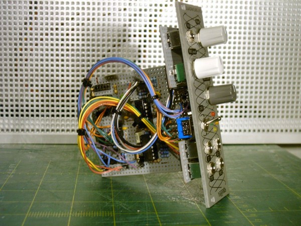
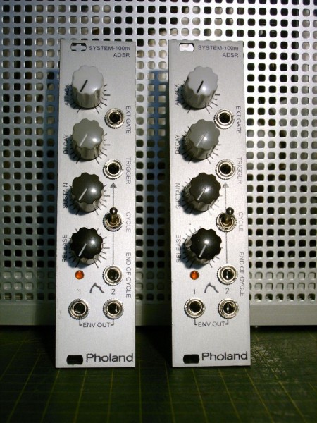
I finished 2 Roland 100m ADSR modules with PCBs from LFLab who added an End of Cycle output to the design. I was immediately curious if it
would be possible to use this output to turn the ADSR into an LFO by connecting this output to the GATE input. I tested it but it didn't work.
So I took a closer look at it and noticed 2 problems. First of all the E.o.C. output is a pulse output and as a result it is usually low. So if you would
connect it to the GATE input it would never trigger the ADSR unless you jumpstart it. Using the output of comparator IC2a instead solves this
problem but there is a second problem. As soon as the ADSR starts its cycle and the output voltages rises the output from this comparator
becomes low and as a result the ADSR immediately goes into Release. So even if it cycles it would be at a fairly high frequency and the output
amplitude would be very low.
To solve this I added a Flip-Flop made with NAND gates. So when the ouput of Comparator IC2a goes low the ouput of the Flip-Flop stays
high preventing the ADSR from going into Release. Of course without resetting the Flip-Flop it would get stuck at Sustain because the GATE
input is still high. Luckely the ADSR already has another comparator that changes state at the end of Attack and I used this to reset the Flip-Flop.
So now it cycles between Attack and Release (it skips Decay and Sustain)
Initially I was only using NAND gates IC3c and IC3d as inverters because the Flip-Flop triggers on a high to low transition. But NAND gates have
2 inputs and because the GATE input isn't connected to the ADSR in cycle mode I can use it to enable/disable the Flip-Flop turning it into a gated
LFO. By adding a resistor btween V+ and the switch connection on the GATE input it will still cycle when nothing is connected. This does have
another effect though which I guess is a bonus feature. In normal ADSR mode when nothing is connected to the GATE input it will get stuck in
Sustain, which means you can set a DC output voltage with the Sustain control. I also added another input between the output of the IC2a
comparator and the input of the Flip-Flop that functions as a trigger input.
This all worked fine but there was one minor issue. The NAND gates need a fairly high voltage to trigger, so using +5V which is pretty standard
for gate outputs wouldn't work. To solve this I added 2 more comparators to the inputs of NAND gate IC3c.
| Description: |
|
| Filesize: |
195.62 KB |
| Viewed: |
646 Time(s) |
| This image has been reduced to fit the page. Click on it to enlarge. |
|
| Description: |
|
| Filesize: |
224.39 KB |
| Viewed: |
624 Time(s) |
| This image has been reduced to fit the page. Click on it to enlarge. |
|
| Description: |
|
| Filesize: |
88.78 KB |
| Viewed: |
723 Time(s) |
| This image has been reduced to fit the page. Click on it to enlarge. |
|
_________________
"My perf, it's full of holes!"
http://phobos.000space.com/
SoundCloud BandCamp MixCloud Stickney Synthyards Captain Collider Twitch YouTube
Last edited by PHOBoS on Mon Nov 21, 2016 5:12 am; edited 1 time in total |
|
|
Back to top
|
|
|
Skrog Productions

Joined: Jan 07, 2009
Posts: 1220
Location: Scottish Borders
Audio files: 159
|
| Posted: Sun Nov 20, 2016 11:46 pm Post subject:
|
|
|
Looks great , love the logo 
Dave. |
|
|
Back to top
|
|
|
alanwilder81
Joined: Sep 03, 2016
Posts: 310
Location: italy
|
| Posted: Mon Nov 21, 2016 4:55 am Post subject:
|
|
|
phobos,
i truly like that ADSR module ! Roland FTW !
i've been a Roland sound fan forever, in particular of the Jupiter 4 and Promars raw filter.
Do you have any Roland filter schematics,be it clone or modification of the original? i've been on the hunt for long, but internet offers 70's schematics which are confusing at best and use obsolete components
I'd be happy with modern schematics of some sort !
cheers |
|
|
Back to top
|
|
|
LFLab
Joined: Dec 17, 2009
Posts: 497
Location: Rosmalen, Netherlands
|
| Posted: Mon Nov 21, 2016 7:50 am Post subject:
|
|
|
VCF's are not ADSR's
But AMsynths has a range of Roland filters, and Frequencycentral has the 100m VCF (system100 vcf), I think most of these have (redrawn) schematics available. |
|
|
Back to top
|
|
|
alanwilder81
Joined: Sep 03, 2016
Posts: 310
Location: italy
|
| Posted: Mon Nov 21, 2016 8:55 am Post subject:
|
|
|
Flab
LOL
i know filters do behave slighty differently from envelope generators . I just took advantage of Phobos coming up with this baby to have some infos. And there we go, you mentioned that company.
Is there any way to get the schemos without having to buy the modules?
I've known about them for long, they are tempting, but they come at a steep price at least for my pocket 
thanks anyway |
|
|
Back to top
|
|
|
L´Andratté
Joined: Sep 23, 2012
Posts: 151
Location: Hamburg, Germany
Audio files: 5
|
|
|
Back to top
|
|
|
alanwilder81
Joined: Sep 03, 2016
Posts: 310
Location: italy
|
| Posted: Mon Nov 21, 2016 10:16 am Post subject:
|
|
|
yes ,those very ones Amazing filters collection !!
i found them long ago,however i think they arent very clear. Or those ancient filters employ hard to find components.
I really wish i could get any of the to work,becasue that's the sound im definitely after |
|
|
Back to top
|
|
|
L´Andratté
Joined: Sep 23, 2012
Posts: 151
Location: Hamburg, Germany
Audio files: 5
|
| Posted: Mon Nov 21, 2016 10:34 am Post subject:
|
|
|
iirc Oliver Gillet has recreated the 4-pole roland style vcf with 13700s on his site mutable instruments, look at the shruti filter boards or ripples, he provides all the schematics...
Edit:http://mutable-instruments.net/shruthi1/build/smr4mkII |
|
|
Back to top
|
|
|
|

 Forum index » DIY Hardware and Software » Stickney Synthyards