| Author |
Message |
PHOBoS

Joined: Jan 14, 2010
Posts: 5890
Location: Moon Base
Audio files: 709
|
 Posted: Sat Aug 26, 2017 6:24 am Post subject:
PHOBoS in SMD land Posted: Sat Aug 26, 2017 6:24 am Post subject:
PHOBoS in SMD land
Subject description: please don't sneeze |
  |
|
A couple of years ago I discovered the Mutable Instruments Braid Module and after watching a demo
I wanted one. I am not able to afford a complete module and I prefer DIY anyway but luckily everything
is made open source (thanks Oliver!). So although a bit tricky it is possible to built my own. I thought
about having the boards made but because they are larger than 100mm the costs go up quickly. I was
contemplating of making some adjustments and maybe leaving the bottom row of sockets off to reduce
the board size but at some point I came across a very cheap PCB at Magpie Modular. I think it was so
cheap because it must have been the last V4 version and I actually received a V5  because of the because of the
shipping costs I also ordered PCBs for Clouds and Rings.
There are 2 things about the The Braids PCB that are a challenge for me, first of all the very small parts
but also the firmware flashing which I am actually more worried about. But let's focus on the SMD
parts for now. I don't have any experience with soldering them except for some 100nF capacitors which
where slightly larger in size. So to prevent screwing up the braids PCB I ordered some practise kits.
The first 2 practise kits I got have a bunch of 1206, 0805, 0603 resistors, some cylindrical 1206 diodes,
SOT-23 transistors and a SOP16 chip. There is also a space for a SSOP28 chip but that one is not included.
The resistors and diodes are wired in series with an LED and there are 2 solder pads for power so you can
test if those parts are soldered correctly. The second practise kit has pretty much the same part but also
has 2 16-pin chips and most importantly 2 chips in a PQFP44 package. It also seems to have resistor arrays
in a 0603 package which should be a nice challenge.
Besides the solder kits I also got some 0.7mm solder (I usually use 1mm), 2 flux pens, which I have
already made some use of and I can recommend it to anybody who does any DIY soldering, a selection of
different soldering tips* and a very crappy probably useless vaccuum placement tool. And to help me out
a bit more I' ll be using a pair of tweezers and a jewelers loupe (15x).
*soldering tips I have are:
900M-T-K (knife shaped)
900M-T-1 (pointy 1mm)
900M-T-3C (horseshoe C shaped 3mm)
900M-T-1C (horseshoe C shaped 1mm)
900M-T-0.5C (horseshoe C shaped 0.5mm)
I'll start with the 900-T-1C to see how well that works. I think for the electrolytic caps on the braids board
the 900-T-0.5C might come in handy.
So wish me luck and any suggestions are welcome (no, I don't have any blu tack alan  ). ).
| Description: |
|
| Filesize: |
360.61 KB |
| Viewed: |
782 Time(s) |
| This image has been reduced to fit the page. Click on it to enlarge. |

|
_________________
"My perf, it's full of holes!"
http://phobos.000space.com/
SoundCloud BandCamp MixCloud Stickney Synthyards Captain Collider Twitch YouTube |
|
|
Back to top
|
|
 |
PHOBoS
Joined: Jan 14, 2010
Posts: 5890
Location: Moon Base
Audio files: 709
|
| Posted: Sat Aug 26, 2017 7:18 am Post subject:
|
|
|
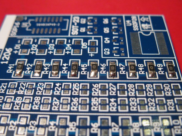
The first 9 1206 resistors are soldered. I have to admit it was already a bit more difficult than I had expected (any tips on
turning over an SMD component ?) but I think I doesn't look too bad. I did clean up most of the joints with some soldering
braid and in some cases applied some fresh solder. By the looks of it I can still use a lot less of it, which is a bit tricky but
I haven't tried flux yet. The soldering joints for R42 and R45 on photo 03 look like what I am aiming for.
Since I have 2 of these boards I will first solder the 1206 resistors on the other board and than probably try the diodes.
| Description: |
|
| Filesize: |
316.34 KB |
| Viewed: |
746 Time(s) |
| This image has been reduced to fit the page. Click on it to enlarge. |
|
| Description: |
|
| Filesize: |
304.95 KB |
| Viewed: |
789 Time(s) |
| This image has been reduced to fit the page. Click on it to enlarge. |

|
_________________
"My perf, it's full of holes!"
http://phobos.000space.com/
SoundCloud BandCamp MixCloud Stickney Synthyards Captain Collider Twitch YouTube |
|
|
Back to top
|
|
|
PHOBoS
Joined: Jan 14, 2010
Posts: 5890
Location: Moon Base
Audio files: 709
|
| Posted: Sat Aug 26, 2017 7:44 am Post subject:
|
|
|
I changed the tip and tried the 900M-T-1 which works a lot easier. The joints are still a bit blobby but I didn't do any cleanup this time.
Flux also seems to help a bit but is not really necessary.
| Description: |
|
| Filesize: |
276.15 KB |
| Viewed: |
769 Time(s) |
| This image has been reduced to fit the page. Click on it to enlarge. |

|
| Description: |
|
| Filesize: |
307.5 KB |
| Viewed: |
778 Time(s) |
| This image has been reduced to fit the page. Click on it to enlarge. |

|
_________________
"My perf, it's full of holes!"
http://phobos.000space.com/
SoundCloud BandCamp MixCloud Stickney Synthyards Captain Collider Twitch YouTube |
|
|
Back to top
|
|
|
PHOBoS
Joined: Jan 14, 2010
Posts: 5890
Location: Moon Base
Audio files: 709
|
| Posted: Sat Aug 26, 2017 8:04 am Post subject:
|
|
|
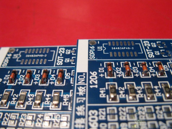
The diodes were not that difficult to solder just slightly tricky to hold with the tweezers. I don't think the Braids module
uses any of these though.
| Description: |
|
| Filesize: |
299.3 KB |
| Viewed: |
769 Time(s) |
| This image has been reduced to fit the page. Click on it to enlarge. |

|
| Description: |
|
| Filesize: |
269.2 KB |
| Viewed: |
751 Time(s) |
| This image has been reduced to fit the page. Click on it to enlarge. |
|
_________________
"My perf, it's full of holes!"
http://phobos.000space.com/
SoundCloud BandCamp MixCloud Stickney Synthyards Captain Collider Twitch YouTube |
|
|
Back to top
|
|
|
gabbagabi

Joined: Nov 29, 2008
Posts: 652
Location: Berlin by n8
Audio files: 23
|
| Posted: Sat Aug 26, 2017 8:06 am Post subject:
|
|
|
smd, what an adventure!
if my memory is still working right i read that one has used flux to "glue" the components to the pcb, which included easyer soldering afterwards
i wish u good luck! |
|
|
Back to top
|
|
|
PHOBoS
Joined: Jan 14, 2010
Posts: 5890
Location: Moon Base
Audio files: 709
|
| Posted: Sat Aug 26, 2017 8:34 am Post subject:
|
|
|
Thanks 
I can see how hat could work with flux but probably not with the stuff I have which is very liquid (low viscosity).
I know there is much thicker flux available which is more like a paste and that might work really well. Of course
there's also actual solder paste which works wondeful in combination with a reflow oven. But without a template
or (expensive) equipment it might be hard to apply the right dosage.
_________________
"My perf, it's full of holes!"
http://phobos.000space.com/
SoundCloud BandCamp MixCloud Stickney Synthyards Captain Collider Twitch YouTube |
|
|
Back to top
|
|
|
blue hell
Site Admin

Joined: Apr 03, 2004
Posts: 24560
Location: The Netherlands, Enschede
Audio files: 304
G2 patch files: 320
|
| Posted: Sat Aug 26, 2017 8:58 am Post subject:
|
|
|
Looks pretty good pho.
re. solder paste - it has a limited shelf life too, even when kept in the fridge.
_________________
Jan
also .. could someone please turn down the thermostat a bit.
 |
|
|
Back to top
|
|
|
PHOBoS
Joined: Jan 14, 2010
Posts: 5890
Location: Moon Base
Audio files: 709
|
| Posted: Sat Aug 26, 2017 9:42 am Post subject:
|
|
|
Thanks jan
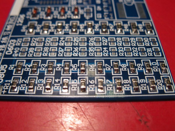
I think the 0805 resistors came out pretty nice. I am using the maginfier in my desklamp now which definitely helps
but also soldering slighly different. I first add a bit of solder to one pad position the component and tag it on then
solder the other pad. But what I've done different this time is that for the other pad I add flux and add a minute
amount of solder to my iron instead of to the pad directly. Sometimes the solder on the plated pads is even enough.
The 0603 resistors are going to be a bigger (or is that smaller) challenge of course.
(yes the resistors are upside down as I initialy thought it said 10E instead of 304)
| Description: |
|
| Filesize: |
252.97 KB |
| Viewed: |
747 Time(s) |
| This image has been reduced to fit the page. Click on it to enlarge. |

|
| Description: |
|
| Filesize: |
303.52 KB |
| Viewed: |
759 Time(s) |
| This image has been reduced to fit the page. Click on it to enlarge. |
|
_________________
"My perf, it's full of holes!"
http://phobos.000space.com/
SoundCloud BandCamp MixCloud Stickney Synthyards Captain Collider Twitch YouTube |
|
|
Back to top
|
|
|
PHOBoS
Joined: Jan 14, 2010
Posts: 5890
Location: Moon Base
Audio files: 709
|
| Posted: Sat Aug 26, 2017 10:15 am Post subject:
|
|
|
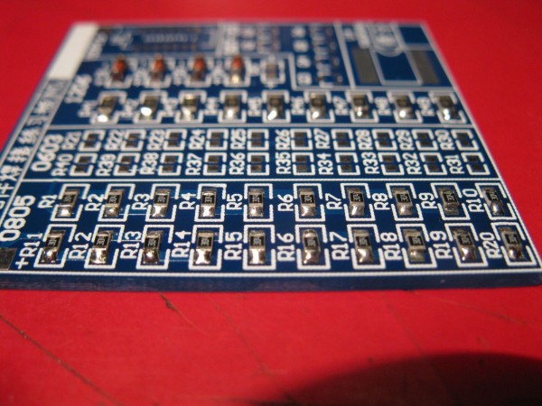
And the other board. I'm not sure if I will do anymore soldering today as it is straining my neck a bit. I can highly recommend
these practise boards for anyone who wants to get into SMD. I got mine for $0.99 (incl shipping) of ebay but you can find
them at other places as well.
| Description: |
|
| Filesize: |
256.16 KB |
| Viewed: |
739 Time(s) |
| This image has been reduced to fit the page. Click on it to enlarge. |

|
| Description: |
|
| Filesize: |
258.83 KB |
| Viewed: |
723 Time(s) |
| This image has been reduced to fit the page. Click on it to enlarge. |
|
_________________
"My perf, it's full of holes!"
http://phobos.000space.com/
SoundCloud BandCamp MixCloud Stickney Synthyards Captain Collider Twitch YouTube |
|
|
Back to top
|
|
|
AlanP
Joined: Mar 11, 2014
Posts: 746
Location: New Zealand
Audio files: 41
|
| Posted: Sat Aug 26, 2017 7:06 pm Post subject:
|
|
|
Don't forget to cut your component leads  |
|
|
Back to top
|
|
|
robsol
Stream Operator

Joined: Apr 24, 2009
Posts: 2514
Location: Bristol UK
Audio files: 500
|
| Posted: Sun Aug 27, 2017 5:49 am Post subject:
|
|
|
That looks really good to me! I think you are ready to move on to nano technology, really maximise your space! 
Are the practice boards useful for anything?
_________________
Muied Lumens Sub Forum
Bandcamp |
|
|
Back to top
|
|
|
PHOBoS
Joined: Jan 14, 2010
Posts: 5890
Location: Moon Base
Audio files: 709
|
| Posted: Sun Aug 27, 2017 6:38 am Post subject:
|
|
|
Thanks bob maybe I can design a NANOlator ?
The boards don't have much use circuitry wise, resistors and diodes are just wired in series but there is an LED for testing.
Too bad they aren't square or you could get 6 and glue them into a cube You could drill a hole in it and use it as a keychain.
But no, besides practising soldering skills there isn't a real use for it.
I just tried the 0603 resistors and these are too small for what I would say is comfortable. Not that it is impossible it actually
went pretty well I think, but 0805 are a nice size for manual handling and soldering. With the 0603 it gets so small that
you quickly have too much solder and positioning is a lot harder. I am pretty sure the Braids PCB uses 0603 but they aren't
really designed for DIY. I also soldered on the LED which was actually a lot harder than I had expected and I really don't
like the solder joints on it. It looks like it is just sitting in the solder, but it works.
| Description: |
|
| Filesize: |
287.49 KB |
| Viewed: |
549 Time(s) |
| This image has been reduced to fit the page. Click on it to enlarge. |

|
| Description: |
|
| Filesize: |
314.51 KB |
| Viewed: |
532 Time(s) |
| This image has been reduced to fit the page. Click on it to enlarge. |

|
| Description: |
|
| Filesize: |
252 KB |
| Viewed: |
555 Time(s) |
| This image has been reduced to fit the page. Click on it to enlarge. |

|
| Description: |
|
| Filesize: |
274.48 KB |
| Viewed: |
539 Time(s) |
| This image has been reduced to fit the page. Click on it to enlarge. |

|
_________________
"My perf, it's full of holes!"
http://phobos.000space.com/
SoundCloud BandCamp MixCloud Stickney Synthyards Captain Collider Twitch YouTube |
|
|
Back to top
|
|
|
gdavis
Joined: Feb 27, 2013
Posts: 359
Location: San Diego
Audio files: 1
|
| Posted: Sun Aug 27, 2017 5:41 pm Post subject:
|
|
|
I use a flux pen. Put on the pads, place the component, a little dab of solder on a clean iron tip, just touch the tip to the pad and edge of component and the solder wicks right in.
_________________
My synth build blog: http://gndsynth.blogspot.com/ |
|
|
Back to top
|
|
|
piedwagtail

Joined: Apr 15, 2006
Posts: 297
Location: shoreditch
Audio files: 3
|
| Posted: Wed Aug 30, 2017 7:39 am Post subject:
|
|
|
I've learnt to solder the 1206 without flux by dropping a blob on one pad and then sliding the resistor in with tweezers. Previous flux and resistors was haphazard.
Diodes wise I made the mistake of choosing some package which is hard work even with the magnifying glass and is a constant source of poor connection.
ICs ,on a sea of flux, I'm happier with anchoring one pin then doing individual pins and only resort to drag when I get in too close or there's too much solder.
Still think it's a production method best suited to being something to get done at the pcb fabrication stage with an oven. When the price is right getting a semi made board must be the answer.
R |
|
|
Back to top
|
|
|
PHOBoS
Joined: Jan 14, 2010
Posts: 5890
Location: Moon Base
Audio files: 709
|
| Posted: Thu Aug 31, 2017 6:44 am Post subject:
|
|
|
| piedwagtail wrote: | | I've learnt to solder the 1206 without flux by dropping a blob on one pad and then sliding the resistor in with tweezers. |
That's how I am doing it at least for one side, the other side I use flux and solder added to the soldering tip.
seems to work pretty good. Positioning is a bit of a hassle sometimes especially with the very small ones as
they stick to the tweezers or the solder pulls them in the wrong direction.
I finished the first two practise boards and will post some more photos later
_________________
"My perf, it's full of holes!"
http://phobos.000space.com/
SoundCloud BandCamp MixCloud Stickney Synthyards Captain Collider Twitch YouTube |
|
|
Back to top
|
|
|
PHOBoS
Joined: Jan 14, 2010
Posts: 5890
Location: Moon Base
Audio files: 709
|
| Posted: Sat Sep 02, 2017 9:20 am Post subject:
|
|
|
A photo of the 2 finished practise boards and I also soldered all the 'easy' parts on to the other board.
| Description: |
|
| Filesize: |
280.96 KB |
| Viewed: |
545 Time(s) |
| This image has been reduced to fit the page. Click on it to enlarge. |

|
| Description: |
|
| Filesize: |
321.2 KB |
| Viewed: |
553 Time(s) |
| This image has been reduced to fit the page. Click on it to enlarge. |

|
_________________
"My perf, it's full of holes!"
http://phobos.000space.com/
SoundCloud BandCamp MixCloud Stickney Synthyards Captain Collider Twitch YouTube |
|
|
Back to top
|
|
|
PHOBoS
Joined: Jan 14, 2010
Posts: 5890
Location: Moon Base
Audio files: 709
|
|
|
Back to top
|
|
|
PHOBoS
Joined: Jan 14, 2010
Posts: 5890
Location: Moon Base
Audio files: 709
|
| Posted: Sat Sep 02, 2017 12:23 pm Post subject:
|
|
|
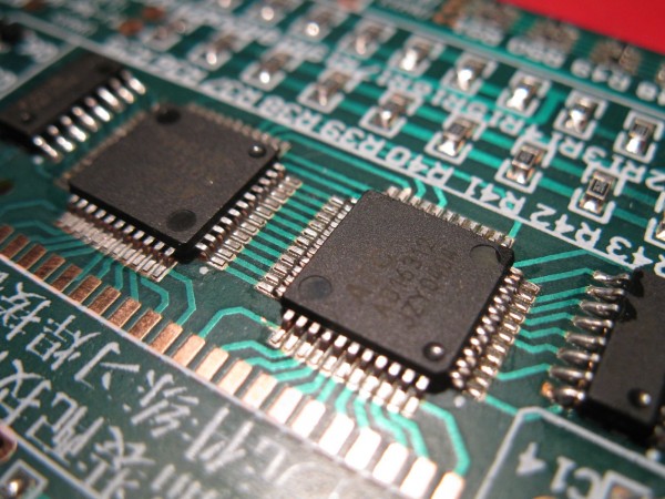
The final components have been soldered on too These were actually rather easy to do, a lot easier
than the resistor arrays. I did one with the regular soldering tip and for the other one I used the knife
shaped tip. The knife shape works perfect if you apply just the right amount of solder but even if you
add too much and wick it away it works really fast so I can recommend it for these kind of chips.
Yes, I bodged the orientation on one, better be careful I don't do any of that stupid stuff on the Braids PCB.
| Description: |
|
| Filesize: |
270.84 KB |
| Viewed: |
539 Time(s) |
| This image has been reduced to fit the page. Click on it to enlarge. |
|
| Description: |
| This side was soldered using the knife shaped tip with just the right amount of solder. |
|
| Filesize: |
247.19 KB |
| Viewed: |
551 Time(s) |
| This image has been reduced to fit the page. Click on it to enlarge. |

|
_________________
"My perf, it's full of holes!"
http://phobos.000space.com/
SoundCloud BandCamp MixCloud Stickney Synthyards Captain Collider Twitch YouTube |
|
|
Back to top
|
|
|
AlanP
Joined: Mar 11, 2014
Posts: 746
Location: New Zealand
Audio files: 41
|
| Posted: Sat Sep 02, 2017 12:30 pm Post subject:
|
|
|
| Good stuff -- only thing I'd add would be to be careful when soldering ICs. It can be quite easy to have a leg that LOOKS like it's soldered, but in fact is not. |
|
|
Back to top
|
|
|
PHOBoS
Joined: Jan 14, 2010
Posts: 5890
Location: Moon Base
Audio files: 709
|
|
|
Back to top
|
|
|
PHOBoS
Joined: Jan 14, 2010
Posts: 5890
Location: Moon Base
Audio files: 709
|
| Posted: Sun Sep 03, 2017 5:57 am Post subject:
|
|
|
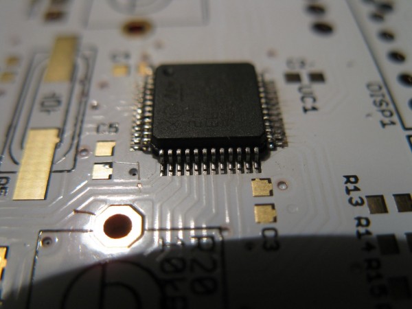
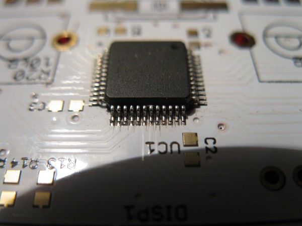
well, there is no turning back now. Of course I immediately screwed up a bit. When I grabbed my soldering iron while focusing
on keeping the chip in the right place I apparently touched the rol of solder (plastic) so when I started soldering I was greeted
by some red molten plastic   . I think the connection is ok though and as you can see in the last photo I tried to clean . I think the connection is ok though and as you can see in the last photo I tried to clean
it up a bit with a (very sharp) dental pick which scratched the soldermask a bit. Something that wasn't helpful with trying to
position it correct is that the soldermask is a bit offset. But all in all I think I could have done a worse job.
| Description: |
|
| Filesize: |
147.74 KB |
| Viewed: |
533 Time(s) |
| This image has been reduced to fit the page. Click on it to enlarge. |
|
| Description: |
|
| Filesize: |
148.49 KB |
| Viewed: |
534 Time(s) |
| This image has been reduced to fit the page. Click on it to enlarge. |

|
| Description: |
| I measured the pin on the right side that doesn't look completely soldered and it's ok. It is actually connected to the GND plane. |
|
| Filesize: |
161.39 KB |
| Viewed: |
560 Time(s) |
| This image has been reduced to fit the page. Click on it to enlarge. |

|
| Description: |
| the molten plastic side with scratches from the dental pick. |
|
| Filesize: |
143.96 KB |
| Viewed: |
567 Time(s) |
| This image has been reduced to fit the page. Click on it to enlarge. |
|
_________________
"My perf, it's full of holes!"
http://phobos.000space.com/
SoundCloud BandCamp MixCloud Stickney Synthyards Captain Collider Twitch YouTube |
|
|
Back to top
|
|
|
PHOBoS
Joined: Jan 14, 2010
Posts: 5890
Location: Moon Base
Audio files: 709
|
|
|
Back to top
|
|
|
gdavis
Joined: Feb 27, 2013
Posts: 359
Location: San Diego
Audio files: 1
|
| Posted: Sun Sep 03, 2017 1:20 pm Post subject:
|
|
|
Oh ya, tough to do with the naked eye.
I use one of those lamps with the magnifying glass in it. The lab I used to work in had microscopes. Then there are those head band magnifiers which I haven't tried myself but seem like a good idea.
Some sort of magnification is very helpful if not a necessity. And good light.
_________________
My synth build blog: http://gndsynth.blogspot.com/ |
|
|
Back to top
|
|
|
PHOBoS
Joined: Jan 14, 2010
Posts: 5890
Location: Moon Base
Audio files: 709
|
| Posted: Sun Sep 03, 2017 1:45 pm Post subject:
|
|
|
yeah it is pretty much impossible to line up without any form of magnification. I have one of those desklamps with a magnifier
too and that definitely helps but it's not enough to really check the connections. A stereo microscope would be ideal but
checking with the camera works pretty well. I know there are also macro USB webcams which would probably be nice for it too.
_________________
"My perf, it's full of holes!"
http://phobos.000space.com/
SoundCloud BandCamp MixCloud Stickney Synthyards Captain Collider Twitch YouTube |
|
|
Back to top
|
|
|
kkissinger
Stream Operator

Joined: Mar 28, 2006
Posts: 1471
Location: Kansas City, Mo USA
Audio files: 45
|
| Posted: Mon Sep 04, 2017 4:22 am Post subject:
|
|
|
PHOBoS,
Beautiful work there!
I have dealt with a little bit of SMD work and feel much fear and trepidation about it.
Thanks for posting!
_________________
-- Kevin
http://kevinkissinger.com |
|
|
Back to top
|
|
|
|

 Forum index » DIY Hardware and Software » Stickney Synthyards


