| Author |
Message |
crazeydazey

Joined: Feb 15, 2007
Posts: 303
Location: England
Audio files: 4
|
 Posted: Sat Jan 11, 2020 1:45 pm Post subject:
Rene Schmitz 4069 VCO Posted: Sat Jan 11, 2020 1:45 pm Post subject:
Rene Schmitz 4069 VCO |
  |
|
Hi,
Wow it's been a while since I've posted here (probs about 8 years  ) ... to be honest I kind of gave in with building stuff and moved on to other crazy idea's like building a life sized R2D2 (don't ask).. anyway I'm back now ) ... to be honest I kind of gave in with building stuff and moved on to other crazy idea's like building a life sized R2D2 (don't ask).. anyway I'm back now 
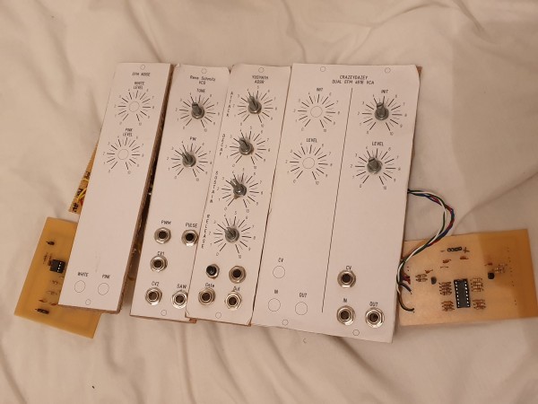
I've just finished building Rene Schmitz 4069 VCO https://www.schmitzbits.de/vco4069.html
and not sure if it works properly, so wanted to check with you guys..
Sawtooth
When the tune (frequency) knob is fully down you can hardly hear anything just very very low frequency (like an LFO - click click etc), which I guess is fine, but then turn it the other way and it doesn't seem to go very high.. It's probably fine, I mean it's high enough, I wasn't expecting to be sending all the local bats crazy or anything just though it might go a bit higher ??
Pulse
Frequency wise pretty much same story as Saw, but then you start to turn up the PW Knob and first 1 or 2 notches it sounds great kinda droney and phazey (nice).. but any further up it just fades out the sound altogether .. does that seem right.?? is it because I'm not actually connecting anything to PWM??
Sorry feel like a total noob as I've been away from this for ages, I can't even remember how it all works
thanks in advance all
daz..
| Description: |
|
| Filesize: |
1.51 MB |
| Viewed: |
508 Time(s) |
| This image has been reduced to fit the page. Click on it to enlarge. |
|
_________________
Nothing is impossible, unless you can't do it!!! |
|
|
Back to top
|
|
 |
JovianPyx

Joined: Nov 20, 2007
Posts: 1988
Location: West Red Spot, Jupiter
Audio files: 224
|
| Posted: Sun Jan 12, 2020 6:50 am Post subject:
|
|
|
Hi Daz,
First check your PSU rails. Then the place to start looking is the CV amplifier and expo converter. Check the component values there, perhaps an R with the wrong value was installed.
Welcome Back! 
_________________
FPGA, dsPIC and Fatman Synth Stuff
Time flies like a banana.
Fruit flies when you're having fun.
BTW, Do these genes make my ass look fat?
corruptio optimi pessima
|
|
|
Back to top
|
|
|
crazeydazey
Joined: Feb 15, 2007
Posts: 303
Location: England
Audio files: 4
|
| Posted: Sun Jan 12, 2020 9:45 am Post subject:
|
|
|
Cheers.. its good to be back
I've checked the resistors, I got a bit carried away and checked them all while I was at it.. They all look fine, some of the colours were a bit hard to tell (my eyesight isn't quite what it was when I first decided i was going to build a synth many many years ago  .. ) i decided to double check them all with the meter and they all seem to be reading ok except some weirdness on the 100k that comes off the tune pot that is saying 25k when the pot is at 0 and 12k when its turn fully round to 10.. i don't get that?? For a start i would have thought turning the tune pot wouldn't make any difference to the value i get putting a meter in parallel to the 100k resistor.. i assumed I'd still just get 100k. .. ) i decided to double check them all with the meter and they all seem to be reading ok except some weirdness on the 100k that comes off the tune pot that is saying 25k when the pot is at 0 and 12k when its turn fully round to 10.. i don't get that?? For a start i would have thought turning the tune pot wouldn't make any difference to the value i get putting a meter in parallel to the 100k resistor.. i assumed I'd still just get 100k.
But that's not really the one I found weird.. it was the PWM that didn't seem to be right not the tune??
What should happen when I turn up the PW pot??
Sorry to confuse anyone here.. I know I'm confused myself
_________________
Nothing is impossible, unless you can't do it!!! |
|
|
Back to top
|
|
|
JovianPyx
Joined: Nov 20, 2007
Posts: 1988
Location: West Red Spot, Jupiter
Audio files: 224
|
| Posted: Sun Jan 12, 2020 10:01 am Post subject:
|
|
|
It's not easy to check part values while in circuit, the parts can interact even when powered down. And yeah, they can do some screwy things while in circuit viewed by a meter.
PWM (or PW) is pulse width. That is, a rectangular pulse is generated from the saw and provided to an output. The PW control changes the width of the pulse. On an oscope, you would see a rectangular pulse that would get wider or thinner when PW is changed. It makes a very nice profound timbre change if you're listening to it.
I'm the person (Scott Gravenhorst) who designed the linear CV version. Unfortunately, I don't know much about how the expo converter works other than it's a voltage controlled current sink. What I do know is that it is what is controlling the discharge current from the oscillator. If the pitch is too low, the current sink isn't sinking enough. How to make it sink more (or less) is what I don't know.
Something I see that looks "odd" in that circuit (but I am certain it is correct - notice the tune pot at the top left. The top of the pot is grounded and the bottom is connected to -V. I don't understand why the top isn't connected to +V, but then I don't know how the module is expected to be used. One thing I would try is to put a few positive volts on the CV in1. That might raise the pitch. It looks like the tune pot is meant to subract from the other 2 CVs. I dunno. It may also be possible to move the tune pot ground connection to +V to give the tune pot a wider range.
_________________
FPGA, dsPIC and Fatman Synth Stuff
Time flies like a banana.
Fruit flies when you're having fun.
BTW, Do these genes make my ass look fat?
corruptio optimi pessima
|
|
|
Back to top
|
|
|
crazeydazey
Joined: Feb 15, 2007
Posts: 303
Location: England
Audio files: 4
|
| Posted: Sun Jan 12, 2020 11:50 am Post subject:
|
|
|
Wow Hi Scott, its an honour to speak to you fine sir... I guess you're a good person to help me here, if Rene himself gives you a mention then I know I'm in good hands
I also checked the PSU rails as you mentioned earlier and don't quite get + and - 15v here, I get something like +15.05v and -14.75v .. is that not good enough? ( if not looks like I'm looking for a new PSU )
I've not tried what you said yet with the Tune pot as wanted to make some vids first to show the problem a bit better.
I managed to get 1 vid done of the Saw but then my phone died whilst recording the Pulse one .. ( so that should be coming soon)
https://youtu.be/T4bYt04LD9o
Again cheers for your help mate (and anyone else that wants to jump in too )
_________________
Nothing is impossible, unless you can't do it!!! |
|
|
Back to top
|
|
|
JovianPyx
Joined: Nov 20, 2007
Posts: 1988
Location: West Red Spot, Jupiter
Audio files: 224
|
| Posted: Sun Jan 12, 2020 12:38 pm Post subject:
|
|
|
Those voltages are fine as long as they are stable.
I had asked Rene for help while I was developing the linear current sink for it. I was getting a nasty "hash" noise in with the sawtooth. Emails back and forth later, Rene gave me the exact pinout he was using. When I wired mine to match - problem solved, no more hash. He's helped me several times with experimental stuff.
Let us know what happens when you put some positive CV in it.
_________________
FPGA, dsPIC and Fatman Synth Stuff
Time flies like a banana.
Fruit flies when you're having fun.
BTW, Do these genes make my ass look fat?
corruptio optimi pessima
|
|
|
Back to top
|
|
|
crazeydazey
Joined: Feb 15, 2007
Posts: 303
Location: England
Audio files: 4
|
| Posted: Sun Jan 12, 2020 12:55 pm Post subject:
|
|
|
Cool 
Yeah forgot to mention that in last post, with positive CV it does take it up higher..
Saw is probably fine then to be fair, I just thought the range was odd.. too low at bottom and not high enough at top but as my first VCO I'm happy with that.. no doubt by the time I'm done (if there is such a thing as being done) , I'll have a few more VCOs in there too. Just went for something simple and tried and tested to start with.
I'll try and get the PW vid done soon, that is the one I'm pretty sure isn't working probably
_________________
Nothing is impossible, unless you can't do it!!! |
|
|
Back to top
|
|
|
JovianPyx
Joined: Nov 20, 2007
Posts: 1988
Location: West Red Spot, Jupiter
Audio files: 224
|
| Posted: Sun Jan 12, 2020 1:11 pm Post subject:
|
|
|
Maybe one of the expo people here will chime in about what you can do to shift the range. It may be working as it should, and it may be modifiable - I don't have expo chops, sorry.
_________________
FPGA, dsPIC and Fatman Synth Stuff
Time flies like a banana.
Fruit flies when you're having fun.
BTW, Do these genes make my ass look fat?
corruptio optimi pessima
|
|
|
Back to top
|
|
|
crazeydazey
Joined: Feb 15, 2007
Posts: 303
Location: England
Audio files: 4
|
| Posted: Sun Jan 12, 2020 2:01 pm Post subject:
|
|
|
No worries mate, cheers for your help..
I've managed to upload the Pulse demo now so you can see what I mean about going quiet...
https://youtu.be/o8o9aIlMnxI
_________________
Nothing is impossible, unless you can't do it!!! |
|
|
Back to top
|
|
|
PHOBoS

Joined: Jan 14, 2010
Posts: 5881
Location: Moon Base
Audio files: 709
|
| Posted: Sun Jan 12, 2020 2:40 pm Post subject:
|
|
|
| JovianPyx wrote: | | Emails back and forth later, Rene gave me the exact pinout he was using. When I wired mine to match - problem solved, no more hash. |
Something related which I was wondering about is if the range problem could have to do with the brand of the chip. Since it is used in a way
that's it's not designed for it wouldn't surprise me if different brands give different results. I have no personal experience with this circuit though
so maybe that has been tested and it should work.
edit: just watched the video and there definitely seems to be something wrong with the PW range. Do you happen to have an oscilloscope ?
_________________
"My perf, it's full of holes!"
http://phobos.000space.com/
SoundCloud BandCamp MixCloud Stickney Synthyards Captain Collider Twitch YouTube |
|
|
Back to top
|
|
|
crazeydazey
Joined: Feb 15, 2007
Posts: 303
Location: England
Audio files: 4
|
| Posted: Sun Jan 12, 2020 2:54 pm Post subject:
|
|
|
I have somewhere if it still works, I've not touched it for years and years though, I probably can't remember how to use it though
what would I be looking for on the scope ?? (sorry really have forgot everything I once knew about electronics treat me like a total noob )
_________________
Nothing is impossible, unless you can't do it!!! |
|
|
Back to top
|
|
|
JovianPyx
Joined: Nov 20, 2007
Posts: 1988
Location: West Red Spot, Jupiter
Audio files: 224
|
| Posted: Sun Jan 12, 2020 3:59 pm Post subject:
|
|
|
Oh I do remember the PW problem. Odd though, I never built that part of the VCO. I had it built on the breadboard with the PW part, but I remember having trouble getting it to work properly. So my final stripboard version of it did not have the PW part. 
That could be PHOBoS, the datasheet from at least one mfr of it printed schematics showing how to use gates like 4069 as linear amplifiers, but I'm not aware of published data regarding their precise characteristics nor performance numbers. There are general rule of thumb kinds of things, like you can sorta control the gain like an opamp using a ratio of Rf : Ri. In that mode, the gates have variable gain, the closer the input is to (Vdd-Vss)/2 the higher the gain, but there's no specific gain values. This is probably because someone played around and found the linear amplifier quirk and put it in the datasheet as a "oh by the way" thing to help sell the chips. I have to say, that part of the datasheet got me thinking.[/code]
It's good to remember that when CMOS gates are used as linear amplifiers, they tend to draw substantial current. Enough can be drawn, that at most one should use only 2 or 3 of the gates in linear amplifier mode. The chip will get hot.
_________________
FPGA, dsPIC and Fatman Synth Stuff
Time flies like a banana.
Fruit flies when you're having fun.
BTW, Do these genes make my ass look fat?
corruptio optimi pessima
|
|
|
Back to top
|
|
|
JovianPyx
Joined: Nov 20, 2007
Posts: 1988
Location: West Red Spot, Jupiter
Audio files: 224
|
| Posted: Sun Jan 12, 2020 4:03 pm Post subject:
|
|
|
What to look for with PW is:
cause the VCO to output a steady frequency.
Measure the PW output with the scope (make sure to ground the VCO to the scope).
When you change the PW pot, the pulse displayed should get wider or narrower.
You want to note things like the minimum and maximum widths. It may need adjusting to make it so that it works from say 1% to 50%. You could go all the way to 99% but 99% is just 1% inverted and would sound the same.
_________________
FPGA, dsPIC and Fatman Synth Stuff
Time flies like a banana.
Fruit flies when you're having fun.
BTW, Do these genes make my ass look fat?
corruptio optimi pessima
|
|
|
Back to top
|
|
|
PHOBoS
Joined: Jan 14, 2010
Posts: 5881
Location: Moon Base
Audio files: 709
|
| Posted: Sun Jan 12, 2020 4:28 pm Post subject:
|
|
|
I am curious what actually happens to the signal when it cuts out. Since there is a DC blocking capacitor on the output you'd have to look
at the signal before that capacitor (pin 7). Not sure if it would tell me much as I am not that great with analog circuits and these aren't real
opamps to begin with so it's all a bit strange. Also when you turn the pot clockwise does that go to to GND or the positive supply ?
Oh and are you sure the transistor is the correct way around ? (you probably checked that a 100 times already but I have to ask)
As for the range, scott might be correct in that it expects a CV input as the pot does indeed seem to subtract. By the looks of it that section
is working correct but I agree with you that it does appear like the range is shifted downwards to what you would expect.
_________________
"My perf, it's full of holes!"
http://phobos.000space.com/
SoundCloud BandCamp MixCloud Stickney Synthyards Captain Collider Twitch YouTube |
|
|
Back to top
|
|
|
crazeydazey
Joined: Feb 15, 2007
Posts: 303
Location: England
Audio files: 4
|
| Posted: Mon Jan 13, 2020 12:33 am Post subject:
|
|
|
Cheers guys, I'll try and find my old scope out and see if still works and see if I can make any sense if the readings and let you know..
I'll also check the tranny (I assume its the T3 one your referring to?) I've not really checked that on any of em to be honest mate
I've checked the PW pot, when turned fully clockwise it goes to +ve
Cheers again chaps..
_________________
Nothing is impossible, unless you can't do it!!! |
|
|
Back to top
|
|
|
crazeydazey
Joined: Feb 15, 2007
Posts: 303
Location: England
Audio files: 4
|
| Posted: Mon Jan 13, 2020 1:59 pm Post subject:
|
|
|
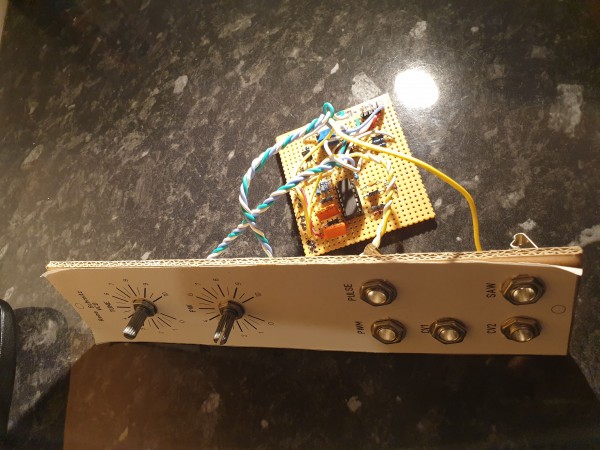
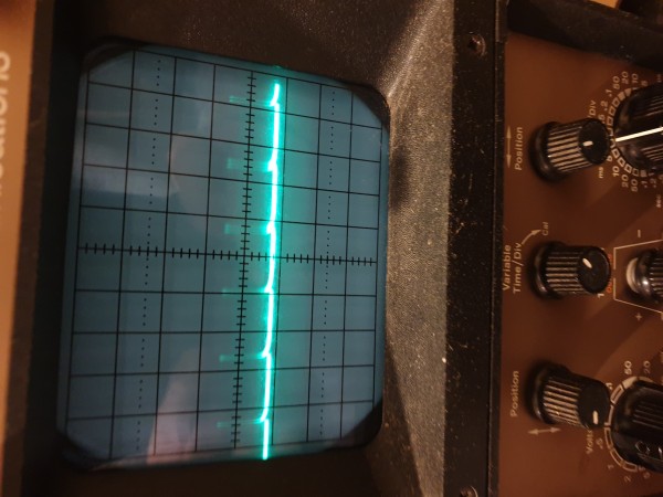
Checked T3 yep it's right way round..
Also got my scope out and took some photos..
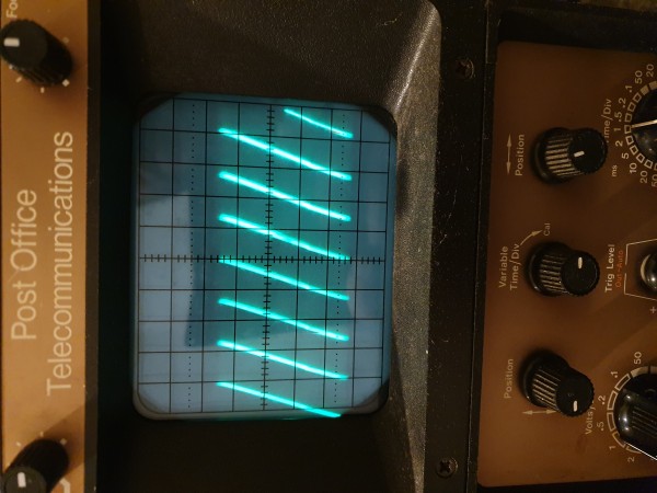
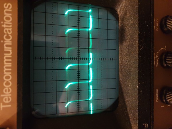
Saw looks like a saw to me and pulse I think looks alright until you turn PW then it just turns into a straight line..
| Description: |
|
| Filesize: |
3.85 MB |
| Viewed: |
268 Time(s) |
| This image has been reduced to fit the page. Click on it to enlarge. |
|
| Description: |
|
| Filesize: |
4 MB |
| Viewed: |
237 Time(s) |
| This image has been reduced to fit the page. Click on it to enlarge. |
|
| Description: |
|
| Filesize: |
3.75 MB |
| Viewed: |
267 Time(s) |
| This image has been reduced to fit the page. Click on it to enlarge. |
|
_________________
Nothing is impossible, unless you can't do it!!! |
|
|
Back to top
|
|
|
JovianPyx
Joined: Nov 20, 2007
Posts: 1988
Location: West Red Spot, Jupiter
Audio files: 224
|
| Posted: Mon Jan 13, 2020 4:53 pm Post subject:
|
|
|
The top image is definitely the saw. Looks nice.
The next one down looks like sort of pulse, not sure why the one edge is curved. Ideally, it should be a rectangular shape. Probably the effect of a capacitor.
With a wet finger in the wind, I keep looking at the 47K resistor that couples the integrator's ramp output to the PW generator. I would replace that with 100K and see what happens. If it extends the range of the PW pot then it helped and maybe could go bigger. If it makes it worse, then maybe something lower than 47K.
Alternatively, the resistor feeding the summing node from the PW pot might need changing. Making the 47K bigger isn't a problem, but smaller would present a lower impedance to the integrator. That's when I'd want to change the 100K coming from the PW pot.
The pulse output looks funny, curious what's going on there.
_________________
FPGA, dsPIC and Fatman Synth Stuff
Time flies like a banana.
Fruit flies when you're having fun.
BTW, Do these genes make my ass look fat?
corruptio optimi pessima
|
|
|
Back to top
|
|
|
crazeydazey
Joined: Feb 15, 2007
Posts: 303
Location: England
Audio files: 4
|
| Posted: Tue Jan 14, 2020 9:53 am Post subject:
|
|
|
Yeah totally agree the pulse looks weird, I was expecting the pulses to be wider and get thinner when I turned the PW clockwise, but they start thin then the pulse is virtually none existent which is why it goes quiet.
I did also wonder about the curve but not for long, my ears aren't good enough to hear it so I could live with that..
I think if I can make it wider initially and then the PW range should get wider I am one happy man
Btw hooked up CV to my midi to CV and played a little sequence.. i was pretty happy with that, managed to tune it fine, range was A LOT higher.
Just need to sort that PW problem and will be very very happy with it
_________________
Nothing is impossible, unless you can't do it!!! |
|
|
Back to top
|
|
|
crazeydazey
Joined: Feb 15, 2007
Posts: 303
Location: England
Audio files: 4
|
|
|
Back to top
|
|
|
flagada
Joined: Dec 15, 2016
Posts: 39
Location: Amsterdam
|
| Posted: Mon Jan 20, 2020 2:29 am Post subject:
|
|
|
Am I missing something here? It is perfectly normal that a PWM rectangular wave stops oscillating as soon as the duty cycle of either the upper or lower part of the wave reaches 100%. You should indeed adjust this by taking the proper resistor values on both sides of the initial PWM potmeter. But then again, if you feed CV into the PWM CV, the oscillation will stop again as soon as the CV causes the duty cycle to reach 100%.
I made this oscillator years ago and I also noticed that the rectangualar wave is not very rectangular, but it is actually like yours. I guess it is inherent to the design. |
|
|
Back to top
|
|
|
crazeydazey
Joined: Feb 15, 2007
Posts: 303
Location: England
Audio files: 4
|
| Posted: Mon Jan 20, 2020 2:52 am Post subject:
|
|
|
I don't know mate I'm still learning .. I just found it really strange that it used to just cut out after hardly turning the PW dial (I would say from 0 to 2 it's ok then nothing after that).
I do understand what your saying about it should cut out when the duty cycle reaches 100%, I just didn't expect to to happen so quick ..
Do you still have yours?? and if so what is your's like (does it cut out at 2??)
i did change the 47K to 22K which made it better, I guess reading your comment I need to change another one too ?? which one and what to?? sorry for all the questions.. as I say I'm just learning.
Though like I say I'm happy with it as it now is so if it can't be fully sorted it's np prob ..
_________________
Nothing is impossible, unless you can't do it!!! |
|
|
Back to top
|
|
|
PHOBoS
Joined: Jan 14, 2010
Posts: 5881
Location: Moon Base
Audio files: 709
|
| Posted: Mon Jan 20, 2020 4:00 am Post subject:
|
|
|
The not-so-square waveform is most likely caused by the DC blocking capacitor on the output.
| Quote: | | i did change the 47K to 22K which made it better, I guess reading your comment I need to change another one too ?? which one and what to?? sorry for all the questions.. as I say I'm just learning. |
You could place a resistor in series with the pot on the side where it connects to +Ub, basically limiting it.
It does seem strange that it cuts out so quick though, but since I haven't build this desing I have no idea if it is supposed to that.
However, going by the schematic it looks like adding a positive CV to control the pulsewidth would make it even worse.
_________________
"My perf, it's full of holes!"
http://phobos.000space.com/
SoundCloud BandCamp MixCloud Stickney Synthyards Captain Collider Twitch YouTube |
|
|
Back to top
|
|
|
flagada
Joined: Dec 15, 2016
Posts: 39
Location: Amsterdam
|
| Posted: Mon Jan 20, 2020 4:17 am Post subject:
|
|
|
I am pretty sure that I did not change the 47K resistor. If I did anything at all it was something like PHOBoS suggested.
| PHOBoS wrote: | | You could place a resistor in series with the pot on the side where it connects to +Ub, basically limiting it. |
I just checked: mine stops oscillating just below nine o clock, and above 4 o clock. |
|
|
Back to top
|
|
|
crazeydazey
Joined: Feb 15, 2007
Posts: 303
Location: England
Audio files: 4
|
| Posted: Tue Jan 21, 2020 6:46 am Post subject:
|
|
|
| flagada wrote: | | I am pretty sure that I did not change the 47K resistor. If I did anything at all it was something like PHOBoS suggested. |
Sorry to be a pain mate, is there any way that you would be able to check what you did so I could give that a try. Although if it is a pain for you (ie you have to dismantle your synth to get to it etc) it's cool, I'll live with it as is
_________________
Nothing is impossible, unless you can't do it!!! |
|
|
Back to top
|
|
|
flagada
Joined: Dec 15, 2016
Posts: 39
Location: Amsterdam
|
| Posted: Thu Jan 23, 2020 12:19 pm Post subject:
|
|
|
| Hi crazeydazey, it is indeed too difficult to dismantle the cabinet in which it resides. But after carefully reading the topic I am sure that my VCO did not have the problem that yours has. I thought yours stopped oscillating below 2, but it stops above 2. I agree that something is not quite OK with your PWM section. Which transistor did you use? You are aware that a 2n3904 has a different pinout than a BC550? |
|
|
Back to top
|
|
|
|

 Forum index » DIY Hardware and Software » The Repair Shop