| Author |
Message |
bubzy

Joined: Oct 27, 2010
Posts: 594
Location: United Kingdom
Audio files: 64
|
|
|
Back to top
|
|
 |
madskill42

Joined: Jun 30, 2011
Posts: 25
Location: czech rep
|
 Posted: Tue Jul 12, 2011 10:28 am Post subject: Posted: Tue Jul 12, 2011 10:28 am Post subject:
|
  |
|
I thought I've already seen this one 
Samples? |
|
|
Back to top
|
|
|
bubzy
Joined: Oct 27, 2010
Posts: 594
Location: United Kingdom
Audio files: 64
|
|
|
Back to top
|
|
|
madskill42
Joined: Jun 30, 2011
Posts: 25
Location: czech rep
|
| Posted: Thu Jul 14, 2011 3:17 pm Post subject:
|
|
|
That's kinda what I meant
Sound pretty cool for two chips. I tried to use 4040 for dividing clock for 4017, but this sound much better! Can you run audio (like sines) through 4040? I can imagine it would sound rather strange
And those diodes makes it sound like Mario's Nightmare! |
|
|
Back to top
|
|
|
mosc
Site Admin

Joined: Jan 31, 2003
Posts: 18240
Location: Durham, NC
Audio files: 224
G2 patch files: 60
|
| Posted: Thu Jul 14, 2011 4:10 pm Post subject:
|
|
|
That is one wild and crazy circuit. Never seen anything quite like it. Sounds great too.
_________________
--Howard
my music and other stuff |
|
|
Back to top
|
|
|
inlifeindeath

Joined: Apr 02, 2010
Posts: 316
Location: Albuquerque, NM
|
| Posted: Thu Jul 14, 2011 6:46 pm Post subject:
|
|
|
| madskill42 wrote: | | Can you run audio (like sines) through 4040? I can imagine it would sound rather strange |
never tried it, but as far as I know, CMOS chips, using digital logic, can only process squarewaves ie. on off/0v Vcc/ 1 0 signals.
_________________
http://www.youtube.com/user/borisandfef |
|
|
Back to top
|
|
|
sndbyte
Joined: Jun 26, 2009
Posts: 119
Location: sf
|
| Posted: Thu Jul 14, 2011 10:06 pm Post subject:
|
|
|
| Hey, that sounds pretty good, thanks for posting. I'm going to have to try breadboarding this circuit this weekend! |
|
|
Back to top
|
|
|
bubzy
Joined: Oct 27, 2010
Posts: 594
Location: United Kingdom
Audio files: 64
|
|
|
Back to top
|
|
|
RingMad

Joined: Jan 15, 2011
Posts: 428
Location: Montreal, Canada
Audio files: 4
|
| Posted: Fri Jul 22, 2011 1:33 pm Post subject:
|
|
|
Thanks for sharing this circuit! I like it a lot! Crazy sounds. I've experimented with pot values and cap values, and there's some interesting stuff. Changing which pins to use on the 4040 gives different stuff too. I'm thinking of putting it in a box.
Since they all have the same pin configuration, I blindly tried swapping the 4011 for a 4070 XOR, 4071 OR, 4077 XNOR and 4081 AND, but none of them produced anything. Maybe I messed something up. |
|
|
Back to top
|
|
|
richardc64

Joined: Jun 01, 2006
Posts: 679
Location: NYC
Audio files: 26
|
| Posted: Fri Jul 22, 2011 2:27 pm Post subject:
|
|
|
| RingMad wrote: | | Since they all have the same pin configuration, I blindly tried swapping the 4011 for a 4070 XOR, 4071 OR, 4077 XNOR and 4081 AND, but none of them produced anything. Maybe I messed something up. |
You didn't mess anything up; you just used the wrong chips 
The 4011 NANDs, which are incorrectly drawn as NORs, are configured as oscillators. A 4070 XOR output will be 0 if both inputs are the same, so in this circuit it won't oscillate. Similarly -- or rather, inversely -- a 4077 XNOR output will be 1 if both inputs are the same, so that won't oscillate here either. The 4071 OR and 4081 AND don't invert, so those will not oscillate.
If you had tried a 4001 NOR it would've worked.
Cool circuit.
_________________
Revenge is a dish best served with a fork... to the eye
Last edited by richardc64 on Fri Jul 22, 2011 2:53 pm; edited 1 time in total |
|
|
Back to top
|
|
|
bubzy
Joined: Oct 27, 2010
Posts: 594
Location: United Kingdom
Audio files: 64
|
| Posted: Fri Jul 22, 2011 2:37 pm Post subject:
|
|
|
they are incorrectly drawn as i just changed the schematic from some 4001's and changed the text on the chip 
i put it down to unadulterated ignorance.
and ty all for the kind words. this may form part of my "i propose a challenge" setup. but if it doesnt its been great fun messing about with these cmos chips. |
|
|
Back to top
|
|
|
RingMad
Joined: Jan 15, 2011
Posts: 428
Location: Montreal, Canada
Audio files: 4
|
| Posted: Fri Jul 22, 2011 4:44 pm Post subject:
|
|
|
| richardc64 wrote: |
You didn't mess anything up; you just used the wrong chips
[... explanations ...]
If you had tried a 4001 NOR it would've worked.
|
Yeah, thanks for the explanations... I figured it had something to do with the logic, but I was too dumb/lazy to work it out in advance. I was just hoping I'd get lucky. Alas, I don't have any 4001's on hand.
Anyhow, I'm playing with the circuit right now. With various mods, it's pumping out a slow beat, which is not completely regular. And I like that.
[edit: added: ] Oh, yeah, I forgot to mention... I've got this plugged into my oscilloscope, and either it just can't keep up, or this thing puts out the bizarrest patterns! Maybe I'll try to do a little video. |
|
|
Back to top
|
|
|
RingMad
Joined: Jan 15, 2011
Posts: 428
Location: Montreal, Canada
Audio files: 4
|
| Posted: Sun Jul 24, 2011 11:21 am Post subject:
|
|
|
OK, after changing cap values, adding a cap switch box for C2, and the configuration of which pins are used on the 4040, i made this little video of my oscilloscope screen whilst i tweaked knobs and switches....
http://youtu.be/BURzs1Gc_QA |
|
|
Back to top
|
|
|
bubzy
Joined: Oct 27, 2010
Posts: 594
Location: United Kingdom
Audio files: 64
|
| Posted: Sun Jul 24, 2011 5:05 pm Post subject:
|
|
|
| heh, i hadn't thought of hooking this up to a scope, looks cool. nice work |
|
|
Back to top
|
|
|
RingMad
Joined: Jan 15, 2011
Posts: 428
Location: Montreal, Canada
Audio files: 4
|
|
|
Back to top
|
|
|
bubzy
Joined: Oct 27, 2010
Posts: 594
Location: United Kingdom
Audio files: 64
|
| Posted: Sat Sep 24, 2011 1:04 pm Post subject:
|
|
|
| cool box, nice sounds. i feel like a proud parent |
|
|
Back to top
|
|
|
jean bender
Joined: Feb 21, 2010
Posts: 139
Location: france
|
| Posted: Sun Sep 25, 2011 4:18 am Post subject:
|
|
|
yeah, great work there.
You can feell proud parent, bubzy, for real !! Your early design is great for experimentation.
Our Yumyum box gives us lots of fun !!
_________________
http://h.a.k.free.fr/
www.electroncanon.org |
|
|
Back to top
|
|
|
micheline
Joined: Mar 11, 2009
Posts: 9
Location: inside a CMOS
|
| Posted: Tue Sep 27, 2011 9:18 am Post subject:
|
|
|
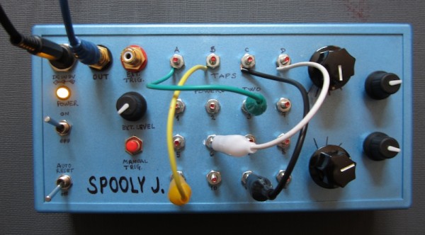
RingMad, this is fantastic! Great crazy sounds!
| Quote: | | 4 tap points and a matrix of terminals, each one connected to a different Q output of the 4040. |
I don't understand what you mean. What are the 4 tap points? How you wire that?
Thanks! |
|
|
Back to top
|
|
|
mosc
Site Admin
Joined: Jan 31, 2003
Posts: 18240
Location: Durham, NC
Audio files: 224
G2 patch files: 60
|
| Posted: Wed Sep 28, 2011 11:38 am Post subject:
|
|
|
 micheline to electro-music.com micheline to electro-music.com
_________________
--Howard
my music and other stuff |
|
|
Back to top
|
|
|
RingMad
Joined: Jan 15, 2011
Posts: 428
Location: Montreal, Canada
Audio files: 4
|
| Posted: Wed Sep 28, 2011 6:26 pm Post subject:
|
|
|
| micheline wrote: | RingMad, this is fantastic! Great crazy sounds!
| Quote: | | 4 tap points and a matrix of terminals, each one connected to a different Q output of the 4040. |
I don't understand what you mean. What are the 4 tap points? How you wire that?
Thanks! |
Thanks and welcome to the forum!
OK, maybe I should draw a schematic of what I built, but I'm leaving town a few days, so it will have to wait. In the meantime, perhaps I can explain referring to Bubzy's schematic...
Firstly, the matrix of "Powers of Two" terminals (bolts) are numbered 1 through 12, and they are wired directly to the corresponding Q output pins of the 4040. e.g. terminal 1 is wired to Q1, terminal 3 is wired to Q3, etc..
Now, on the schematic... see the wire between pin 9 of the 4040 and the anode of D2? Well, instead of connecting it to pin 9, I connect it to my tap point "D" terminal. Now, with the alligator clip on that terminal, I can make the same connection as in the schematic (i.e to pin 9, which is Q1) by clipping it onto the "1" terminal. Or, I could connect it to any of the other Q outputs, thus making it more flexible.
HTH |
|
|
Back to top
|
|
|
micheline
Joined: Mar 11, 2009
Posts: 9
Location: inside a CMOS
|
| Posted: Wed Sep 28, 2011 8:09 pm Post subject:
|
|
|
Hi! Thanks for the welcoming ! This is a great forum. Sorry, I should have said hello before posting, I was too excited by that Spooly Master !
Thanks RingMad for taking the time to explain it. I'm not sure though about the "D" Terminal. If you don't mind drawing a schematic, I'll be more than happy. If you don't, I'll come back with some questions...
Many thanks!
Micheline |
|
|
Back to top
|
|
|
RingMad
Joined: Jan 15, 2011
Posts: 428
Location: Montreal, Canada
Audio files: 4
|
| Posted: Thu Sep 29, 2011 4:45 am Post subject:
|
|
|
| micheline wrote: | | I'm not sure though about the "D" Terminal. |
Look at the photo of my box above... one of the terminals (bolts) is labelled "D". I'll draw a schematic when I get back next week....
J. |
|
|
Back to top
|
|
|
RingMad
Joined: Jan 15, 2011
Posts: 428
Location: Montreal, Canada
Audio files: 4
|
|
|
Back to top
|
|
|
micheline
Joined: Mar 11, 2009
Posts: 9
Location: inside a CMOS
|
| Posted: Fri Oct 07, 2011 11:33 am Post subject:
|
|
|
Yeaaaaah ! RingMad, thank you so much for that. I really appreciated it. I'll try it in a couple of days when I got home.
Many many thanks to you as well as bubzy ! |
|
|
Back to top
|
|
|
micheline
Joined: Mar 11, 2009
Posts: 9
Location: inside a CMOS
|
| Posted: Fri Oct 14, 2011 1:37 pm Post subject:
|
|
|
Hi!
I know this is a simple circuit, I thought I would be able to do it but I have to confess that my reading skills for schematic are zero. Does someone have a picture of the breaboard finished? I would be a great help for learning ... |
|
|
Back to top
|
|
|
|

 Forum index » DIY Hardware and Software » Lunettas - circuits inspired by Stanley Lunetta