Joined: Jan 14, 2010 Posts: 5884 Location: Moon Base
Audio files: 709
Posted: Sat Mar 31, 2012 7:36 am Post subject:
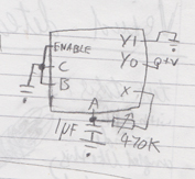
The Jingler Subject description: noisy and bleeping sounds from a single 4051 chip
nice idea, played around a bit with it and ended up with a circuit I called the Jingler
I noticed the sound depend a lot on the powersupply, it likes it a bit dirty, so that's why I put in a 1 ohm resistor.
Don't place a decoupling cap over the chip! you can experiment a bit with the values to get some different sounds
but I'll leave it like this. I used a HEF4051 chip myself, I have no idea if it will work and how it will sound with another chip.
might record some sounds later.
Jingler.gif
Description:
noisy and bleeping sounds from a single 4051 chip
Filesize:
45.35 KB
Viewed:
1040 Time(s)
This image has been reduced to fit the page. Click on it to enlarge.
Joined: Nov 10, 2011 Posts: 878 Location: Lancashire, England
Audio files: 14
Posted: Sat Mar 31, 2012 8:03 am Post subject:
That is brilliant ... I have a circuit named after my username I feel like a professional now!!! Thankyou!
Can we get some further explanation of the operation of your circuit please?
Mine is simple, A switches between Q1 and Q0, or Y1 and Y0 whatever you want to call them; the first two inputs/outputs. It switches X (the common output) to Q1 when A is 1 and Q0 when A is 0, so I just connected Q0 to 1 (or high) and Q1 to 0 (or low), then X to A. This produces very very very high frequency oscillation, the CR network merely causes a delay as the cap charges/discharges giving you a slower oscillation.
I couldn't get this to work again, probably because my supply was nice and clean
Love seeing your work phobos Keep it up _________________ As a mad scientist I am ruled by the dictum of science: "I could be wrong about this but lets find out"
Joined: Jan 14, 2010 Posts: 5884 Location: Moon Base
Audio files: 709
Posted: Sat Mar 31, 2012 8:59 am Post subject:
JingleJoe wrote:
Can we get some further explanation of the operation of your circuit please?
LOL, ehmmm
well I took your idea and used that on the other inputs aswell, so I have
A0 oscillating with Y0, Y1 (when A1, A2 are low)
A1 oscillating with Y0, Y2 (when A0, A2 are low)
A2 oscillating with Y0, Y4 (when A0, A1 are low)
I added one side of the pots to ground with a resistor because this seemed to give some wider range on the pots.
But most of it is just done by experimentation and I have no idea what's really happening. (I think the 4051 doesn't know what's happening to it either )
here are some sounds I recorded last night while working on it, it changed a bit since but gives you a general idea.
Joined: Nov 10, 2011 Posts: 878 Location: Lancashire, England
Audio files: 14
Posted: Sat Mar 31, 2012 12:30 pm Post subject:
I see now! It all makes sense
PHOBoS wrote:
I think the 4051 doesn't know what's happening to it either
hahahahaha Fantastic If the chip could talk I bet it would sound like this mountain:
I allways feel a bit guilty or somehow like I've done something bad when I just experiment without knowing what I'm doing. I feel like I have to figure things out and understand them completely before I can do them. But without that kind of experimentation everything would be boring, a dilemma for myself. Anyways, I work around it somehow
At first your sound file didnt all download for some reason, but I am downloading it all now, so far "jingler" sounds like the least appropriate name for it ever Therefore, I approve.
... my god this thing sound amazing are you using the LDR much? I am making one
P.S. I think there may be a mistake in your diagram; should A0 be connected to Y1? _________________ As a mad scientist I am ruled by the dictum of science: "I could be wrong about this but lets find out"
Joined: Jan 14, 2010 Posts: 5884 Location: Moon Base
Audio files: 709
Posted: Sun Apr 01, 2012 6:01 pm Post subject:
JingleJoe wrote:
hahahahaha Fantastic If the chip could talk I bet it would sound like this mountain:...
ROFL, yes exactly!
Quote:
I allways feel a bit guilty or somehow like I've done something bad when I just experiment without knowing what I'm doing. I feel like I have to figure things out and understand them completely before I can do them. But without that kind of experimentation everything would be boring, a dilemma for myself. Anyways, I work around it somehow
heh, allthough I don't even know that much about electronics, I sometimes think it get's in the way of discovering new things.
so don't feel guilty I'm jealous
Quote:
P.S. I think there may be a mistake in your diagram; should A0 be connected to Y1?
hmm, no I don't see any mistakes except for a dot missing on the ground connection of pin5.
but,..
I couldn't resist trying some oscillators attached to some of the Q/Y pins = more fun
so that's gonna be 4 oscillators build around a 4093 with indicator LED's
(maybe LDR's for speed control if you want to get really crazy)
connected to pins 15, 12, 1, 5
and a switch to still connect them to ground aswell
(this might also help to get some noise on the powerlines) _________________ "My perf, it's full of holes!" http://phobos.000space.com/ SoundCloudBandCampMixCloudStickney SynthyardsCaptain ColliderTwitchYouTube
Joined: Nov 10, 2011 Posts: 878 Location: Lancashire, England
Audio files: 14
Posted: Mon Apr 02, 2012 5:15 am Post subject:
Just thinking about adding the supply noise to kick start this oscillator; maybe we could add a tiny resistor on the ground pin of the chip creating an artificial ground loop? Or maybe a transistor connected accross the power supply with the base left unconnected?
I can't wait to give this a try, I fried a 4051 recently but I have another one which I'll try all your ideas with
P.S. I realized where I misunderstood your diagram, hours later when I was away from the computer _________________ As a mad scientist I am ruled by the dictum of science: "I could be wrong about this but lets find out"
Really cool stuff, the kind of "out of the box" thinking I love. And it sounds quite good aswell, really different and interesting.
Quote:
Quote:
I allways feel a bit guilty or somehow like I've done something bad when I just experiment without knowing what I'm doing. I feel like I have to figure things out and understand them completely before I can do them. But without that kind of experimentation everything would be boring, a dilemma for myself. Anyways, I work around it somehow
heh, allthough I don't even know that much about electronics, I sometimes think it get's in the way of discovering new things.
so don't feel guilty I'm jealous
Exactly! I can appreciate proper design as much as the next guy but generally speaking I just can't be bothered. I would never have known anything about electronics if it wasn't for the lunetta approach of just experimenting and having fun. It's not rocket science . _________________ There he goes. One of God's own prototypes. A high-powered mutant of some kind never even considered for mass production. Too weird to live, and too rare to die.
Hunter S. Thompson movies noise
Joined: Jan 14, 2010 Posts: 5884 Location: Moon Base
Audio files: 709
Posted: Mon Apr 02, 2012 9:44 am Post subject:
o and as for noisy power how's this idea:
just put a CMOS chip on top of it (16 pin)
and only connect the powerpins to the 4051, leave all the other pins floating.
Joined: Nov 10, 2011 Posts: 878 Location: Lancashire, England
Audio files: 14
Posted: Mon Apr 02, 2012 2:05 pm Post subject:
That is such a fucking sound discombobulator Hopefully parts arrive tomorrow, then I will be able to finish my current devices and work on one of these crazy things _________________ As a mad scientist I am ruled by the dictum of science: "I could be wrong about this but lets find out"
Joined: Jan 14, 2010 Posts: 5884 Location: Moon Base
Audio files: 709
Posted: Sun Apr 08, 2012 6:24 am Post subject:
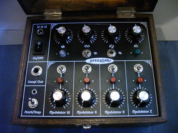
I just finished the jingler and as I kinda expected it sounds nothing like it did on breadboard , but it still makes some noise.
I did add a 100 ohm pot for starve (wish I did that before I finished it and put it on the panel), but that still doesn't give me all those nice sounds.
I might replace the 100uF cap, I know it made a huge difference what size cap I used on the breadboard.
btw modulating pin 1 has a very prominent effect so I added an extra jack for an external CLk. (using the switch contact on the jack
to change from the internal LFO to external)
anyway, here's the 'final' schematic, you can always expand and change whatever you like off course,
and a photo. (I'll post 2 more in the 2012 build thread).
hmm, I just realized I haven't tested with the same PSU I used when breadboarding. And I think there migth be
something wrong with that one causing the voltage to fluctuate more than usual.
Which makes me think of making a LM317 based supply but adding some kind of noise source so the voltage will vary
Jingler2.gif
Description:
Filesize:
81.47 KB
Viewed:
985 Time(s)
This image has been reduced to fit the page. Click on it to enlarge.
Jingler - 04.jpg
Description:
Filesize:
80.75 KB
Viewed:
766 Time(s)
This image has been reduced to fit the page. Click on it to enlarge.
Joined: Nov 10, 2011 Posts: 878 Location: Lancashire, England
Audio files: 14
Posted: Sun Apr 08, 2012 2:56 pm Post subject:
That is friggen awesome I can't believe I inspired this!
This is seriously like the first time I have really invented a circuit, I mean it;s just a funny relaxation oscillator (I think) but I figured out how to combobulate it with this chip so I am very happy with this !!!
Your device looks simply amazing! What will it's fate be?
I have yet to make one of these I don't know where all my time goes! I'll do it tomorrow though because the bank and the post office are shut so I can't get anything done bloody zombie. Why does that mean there is no post?! I need to post things, damnit! Anyways ...
Keep up the good work I'd love to hear some of this one even if it does sound different How much did that cost to build too? _________________ As a mad scientist I am ruled by the dictum of science: "I could be wrong about this but lets find out"
Yingler all the way is the most interesting set of lunetta sounds I've heard in a long time. Really reminds me of some of the experiments I did with chaining lots of XOR gates. _________________ There he goes. One of God's own prototypes. A high-powered mutant of some kind never even considered for mass production. Too weird to live, and too rare to die.
Hunter S. Thompson movies noise
Joined: Nov 10, 2011 Posts: 878 Location: Lancashire, England
Audio files: 14
Posted: Mon Apr 09, 2012 7:52 am Post subject:
Unfortunately I can't get the damn thing to work again, well it for a bit, but its so unstable I can't make it work. I'm glad someone got a good circuit out of this idea though
The circuit oscillated better when I disconnected the potentiometer (refering to my initial diagram).
I've come up with some new things I want to try which might acctually work when you try to do them again, so this circuit can wait. _________________ As a mad scientist I am ruled by the dictum of science: "I could be wrong about this but lets find out"
Joined: Jan 14, 2010 Posts: 5884 Location: Moon Base
Audio files: 709
Posted: Thu Apr 26, 2012 3:53 pm Post subject:
thanks tjookum, I did recently hear some of your sounds on the stream which reminded me of the jingler
I wanted to reply sooner but got distracted by a new VCO design
I did get it to jingle again,. allthough not sompletely the same as breadboarded.
my first idea was to make a varying supply voltage for the 4051 chip so I wired up
a semi random generator used to turn a transistor on/off which switched the supply voltage.
I also added a cap and some extra biasing resistors so it would produce a smooth voltage.
It kinda worked and I thought instead of the random generator it might also be fun to use
a combination of the modulators. So I detached the random generator and to my
surprise it still kept "jingling". So I soldered just the transistor resistors and cap onto
the jingler PCB (there was a bit of of room left), turned it on and,...
After that I had to do a lot of experimenting to find out why it didn´t work and
eventually ended up with adding an extra wire to the DC input just to power the chip
I did record some sounds but it´s ± 100min right now so I might have to edit it a bit,
however I just posted something else which includes some jingler sounds too, here.
as for the total cost of the finished jingler, the parts you see are the most expensive bits and I used reverse log pots
for the modulators which are €2,30 a piece. a bit pricey (the other pots are €0,50) but reverse log just works so
much nicer with these kind of oscillators. You could just use a normal log. too off course and wire it so the oscillator
goes faster when you turn it CCW. All together I think pots, knobs, switches, connectors, LED covers would
come to a total of ± €25,- and probably ± €10,- for the rest.
You cannot post new topics in this forum You cannot reply to topics in this forum You cannot edit your posts in this forum You cannot delete your posts in this forum You cannot vote in polls in this forum You cannot attach files in this forum You can download files in this forum

 Forum index » DIY Hardware and Software » Lunettas - circuits inspired by Stanley Lunetta