| Author |
Message |
hedefalk
Joined: Aug 29, 2017
Posts: 51
Location: Stockholm, Sweden
|
 Posted: Thu Nov 02, 2017 9:41 am Post subject:
Debugging MFOS Dual VCA Posted: Thu Nov 02, 2017 9:41 am Post subject:
Debugging MFOS Dual VCA |
  |
|
Hi, I'm debugging an MFOS dual VCA I've built on protoboard. It's really hard since I don't really know what to look for. I get surprised by some of the measurements but then again I've been surprised before with working circuits I don't fully understand.
So, one of the channels is completely dead on output. I've been focusing on the other one that at least has output, and when I have fixed that one I can A/B check on measure points to pin-point what's wrong with the first.
So, for the one that works, I have attached measurements. The attenauation seems to be working because I can control the amplitude quite fine on the linear side, but I only have a square wave on a sinus input:
So:
*channel 1 log - flatline
*channel 1 lin - flatline
*channel 2 log - flatline
*channel 2 lin - attenuation works, but the audio signal is turned into a square wave.
Any help on what to look for is highly appreciated. I've been poking around with my scope for hours, but simply have no clue.
* I have 0-250mV (turning the pot) going into U1-D's inverting output
* -10.5V to -1V going out of the same opamp (pin 14)
* after this is pushed against the negative rail, I have around -6 to -10V on the linear side of the switch. But only if floating, If I chose linear to connecto to the OTA pin 1, it's going down to -10.5 to -10V.
Anyway, this is for the "working" linear part of one of the VCA's that seem to do about right in the amplification part - I can turn the amplitude up and down with the pot. However, it turns the signal into a square  So there have to be something wroing in the very small OTA-part that I don't understand too… So there have to be something wroing in the very small OTA-part that I don't understand too…
| Description: |
|
| Filesize: |
1.78 MB |
| Viewed: |
618 Time(s) |
| This image has been reduced to fit the page. Click on it to enlarge. |

|
| Description: |
|
| Filesize: |
1.06 MB |
| Viewed: |
572 Time(s) |
| This image has been reduced to fit the page. Click on it to enlarge. |

|
| Description: |
|
| Filesize: |
1.56 MB |
| Viewed: |
565 Time(s) |
| This image has been reduced to fit the page. Click on it to enlarge. |

|
|
|
|
Back to top
|
|
 |
hedefalk
Joined: Aug 29, 2017
Posts: 51
Location: Stockholm, Sweden
|
| Posted: Thu Nov 02, 2017 9:52 am Post subject:
|
|
|
I have a non-inverting input on pin 3 of the OTA which seem to do around 1.5V Pk-Pk. Is that too much?
Oh, yes it was. Love how posting question gives you the solution sometimes. TRIMA was turn way to far which made the difference on the inputs too big -> disting towards square. Sometimes I hate those multi turn trims because I'm too lazy to test the full range. |
|
|
Back to top
|
|
|
hedefalk
Joined: Aug 29, 2017
Posts: 51
Location: Stockholm, Sweden
|
| Posted: Thu Nov 02, 2017 9:57 am Post subject:
|
|
|
Ok, I'll just sit here and turn this knob a few hours until I have the energy to take on the next three:
https://photos.app.goo.gl/Inr3ih1TvZAnTzFh1
* Channel 1 Log - dead
* Channel 1 Linear - dead
* Channel 2 Log - dead
* Channel 2 Linear - WORKING!! |
|
|
Back to top
|
|
|
hedefalk
Joined: Aug 29, 2017
Posts: 51
Location: Stockholm, Sweden
|
| Posted: Fri Nov 17, 2017 5:24 am Post subject:
|
|
|
After much pain and relentless debugging I got it working. Yey!
I had done so many different errors when protoboarding this. I think my big lesson is to never ever protoboard anything this big on such a small board with so little planning.
I mean, look at this mess. I started out with no plan at all and just started placing components. Hubris.
I also burnt quite a few LM13700 - actually only one side of them and that was probably the reason why it took me so long to realise.
Just a list of stuff that I had done wrong as a reminder to myself:
1) debugging a broken LM13700 for ages
2) Not connected the 3904 base to the output of the first cv buffer.
3) mixed up channels when fallbacking to wires - the logA/linB on one side and logB/linA on the other for total confusion.
4) Wrong values for the 2K trimmers (was 20K). Not sure about that one, if I actually made that on purpose for now when trimming to have as little cv bleedtrhough as possible I actually hit ccw limit on them. Not sure yet if this is 2K or 0 ohms yet, but if 2K it would have been good with a higher value.
Actually I think I'm not going to protoboard much at all from now on. I've been building a few utils to be able to have a little more permanent breadboard modules and go straight from that to real pcb's. It's just to messy when trying to make things small too…
Thanks,
Viktor
| Description: |
|
| Filesize: |
2.58 MB |
| Viewed: |
633 Time(s) |
| This image has been reduced to fit the page. Click on it to enlarge. |

|
| Description: |
|
| Filesize: |
2.42 MB |
| Viewed: |
586 Time(s) |
| This image has been reduced to fit the page. Click on it to enlarge. |

|
| Description: |
|
| Filesize: |
1.75 MB |
| Viewed: |
605 Time(s) |
| This image has been reduced to fit the page. Click on it to enlarge. |

|
|
|
|
Back to top
|
|
|
wackelpeter
Joined: May 05, 2013
Posts: 461
Location: germany
Audio files: 10
|
| Posted: Fri Nov 17, 2017 7:41 am Post subject:
|
|
|
Well that indeed looks a little messy on the board, but as long as it's working now... stick it in nobody will notice... 
As a year long stripboard builder and always using self built cases and suit cases i don't know if it would be maybe more easy to use stripboards and then maybe panel mounted knobs and jacks.
Guess there are some people here, who have build proper DIY modules without etched boards and have more of their experiences to share.
_________________
https://soundcloud.com/bastian-j |
|
|
Back to top
|
|
|
hedefalk
Joined: Aug 29, 2017
Posts: 51
Location: Stockholm, Sweden
|
| Posted: Fri Nov 17, 2017 11:31 am Post subject:
|
|
|
I considered using this kinds of boards to do quick but permanent prototypes after feeling I have something feasible on the breadboard. Thing was that I started out with so many different projects and I had about ten breadboards lying around and I started to loose memory of what each one even was. And they fall apart and stuff. But these proto's haven't been that quick for me since I've made so many mistakes I think my main problem was just not planning (because that's boring) and wanting to make it really small because eurorack. I haven't tried stripboards for these projects, but I've used these breadboard looking protoboards. Felt nice since I could imitate a breadboard layout pretty much 1-1. But not really since there wasn't 5 connections on each side, but maybe 3+4 I think which made the whole 1-1 fall apart a bit.
My idea now is to cater for more half-permanent experiments on breadboards. Things like
* just labelling them with a Dymo
* cutting down the length of component pins so they don't fall out as easily
* sticking actual jacks into the breadboard for ins and outs (thonkiconn's)
* having a power rails standard for my breadboards
* Maybe solder a few pots with pins that stick a little better
Stuff like that so I can have working stuff on a breadboard for a while and interfacing with my rack.
And I have been learning KiCad so when I'm happy with something on the breadboard I'll "just" do a double sided PCB and order it from dirtypcbs or oshpark if it's small
Also just ordered a small CNC mill to mill PCB's. Let's see how that turn out
Also considering toner transfer method. Felt it was going to be hard to align for double sided but just realized that if I just drill a few holes first, aligning against the holes would be super easy…?
Waay off topic here |
|
|
Back to top
|
|
|
LFLab
Joined: Dec 17, 2009
Posts: 497
Location: Rosmalen, Netherlands
|
| Posted: Fri Nov 17, 2017 3:15 pm Post subject:
|
|
|
I have this circuit on a little PCB, and I think I have some left. PM me if you are interested, it may have SMT parts, but I can solder these for you if needed.
Edit:
checked, and yes I have plenty of boards left, and yes it does have the IC's in SMT, also, it is a dual, but only log, so not switchable between LOG/LIN. |
|
|
Back to top
|
|
|
linwop
Joined: Mar 24, 2018
Posts: 7
Location: Switzerland
|
| Posted: Fri May 04, 2018 10:04 am Post subject:
|
|
|
Hi all. I'm pretty new to DIY audio electronics. I've built the henry 555 VCO with the PCB and now I want to build this VCA to get some control over the VCO signal 
This is actually the first module I'm trying to build from a schematic.
I've breadboarded the circuit for the second time and I'm pretty sure I've got all the components and connections right.
However i have a problem with Rays instructions to adjusting the trimmers.
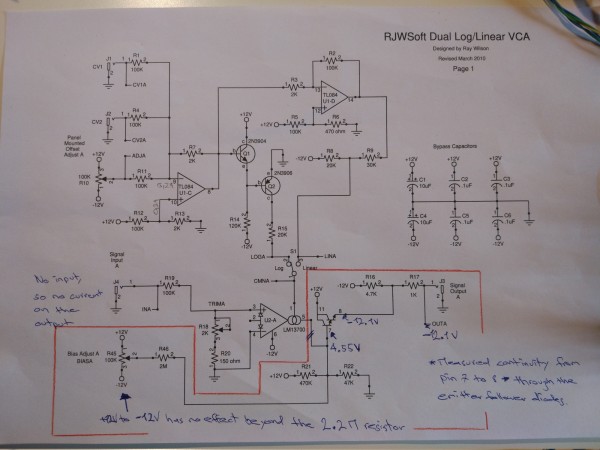
I've set R10/R32 to 0V as he suggest as a first step.
The problem lies at setting R45/R47:
I can apply any voltage I want from -12V to +12V with the bias adjust, but I only get a constant -12V on the signal output.
I have neither CV, signal in or signal out attached to the circuit.
I didn't have a 2M resistor at hand for R46/48 so I substituted with a 2.2M resistor.
I don't really get the part of the circuit after the output of the OTA.
I guess it's purpose is to translate the VC current back to a voltage!?
Would be very thankful if someone could hint me in the right direction. |
|
|
Back to top
|
|
|
RF

Joined: Mar 23, 2007
Posts: 1502
Location: Northern Minnesota, USA
Audio files: 28
|
| Posted: Fri May 04, 2018 4:35 pm Post subject:
|
|
|
I would suspect a bad LM13700 right off the top of my head.
Good luck!
_________________
www.sdiy.org/rfeng
"I want to make these sounds that go wooo-wooo-ah-woo-woo.”
(Herb Deutsch to Bob Moog ~1963) |
|
|
Back to top
|
|
|
linwop
Joined: Mar 24, 2018
Posts: 7
Location: Switzerland
|
|
|
Back to top
|
|
|
linwop
Joined: Mar 24, 2018
Posts: 7
Location: Switzerland
|
|
|
Back to top
|
|
|
RF
Joined: Mar 23, 2007
Posts: 1502
Location: Northern Minnesota, USA
Audio files: 28
|
| Posted: Sun May 06, 2018 8:19 am Post subject:
|
|
|
My suggestion was based on my general method of troubleshooting. You seem
pretty sure of the wiring being correct - my first steps in troubleshooting are checking for wiring errors, soldering joints or solder bridges, polarity of components, correct values of components, orientation of IC's and then IC's themselves. I've had a couple of cases where I see rail voltages at outputs when IC's have been faulty - it's usually easy to substitute a socketed IC in the circuit before I start tracing voltages and trying to understand every part of the circuit. It looks like you are going at it in a very logical way - just a little different than what I start with. Good luck - you will find the problem if you keep at it.
_________________
www.sdiy.org/rfeng
"I want to make these sounds that go wooo-wooo-ah-woo-woo.”
(Herb Deutsch to Bob Moog ~1963) |
|
|
Back to top
|
|
|
RF
Joined: Mar 23, 2007
Posts: 1502
Location: Northern Minnesota, USA
Audio files: 28
|
| Posted: Mon May 21, 2018 3:08 pm Post subject:
|
|
|
Did you get this working linwop?
_________________
www.sdiy.org/rfeng
"I want to make these sounds that go wooo-wooo-ah-woo-woo.”
(Herb Deutsch to Bob Moog ~1963) |
|
|
Back to top
|
|
|
|

 Forum index » DIY Hardware and Software » MusicFromOuterSpace.com designs by Ray Wilson