| Author |
Message |
funkyfarm

Joined: Jan 21, 2007
Posts: 583
Location: France
Audio files: 3
|
 Posted: Tue Dec 30, 2008 10:27 am Post subject: Posted: Tue Dec 30, 2008 10:27 am Post subject:
|
  |
|
| Oh thank you so much ! |
|
|
Back to top
|
|
 |
LetterBeacon
Joined: Mar 18, 2008
Posts: 454
Location: London, UK
|
| Posted: Wed Dec 31, 2008 4:17 am Post subject:
|
|
|
| AndyR1960 wrote: | I've not had a problem using the same PDF - Please remember not to select the Shrink (or Fit) to Page scaling option if you're using Acrobat - make sure you select page scaling as "None", as this will definitely reduce the image... maybe that's the problem?
Cheers,
Andy. |
Just to confirm that the PDF is fine if you un-select Shrink To Fit. I attempted to etch this yesterday and the IC sockets matched up perfectly with the holes.
Unfortunately, as this was my first time with Press N Peel, I managed to mess it up, and not all of the design melted onto the copper - damn! Back to the drawing board...  |
|
|
Back to top
|
|
|
ericcoleridge

Joined: Jan 16, 2007
Posts: 889
Location: NYC
|
| Posted: Thu Jan 01, 2009 7:26 pm Post subject:
|
|
|
I count 6 100k trimpots on this PCB. Could I substitute 50k for any(or all) of these trims without sacrificing tracking?
On the parts placement document, it looks like these are multi-turn trims. But I'm guessing on the odyssey these wre horizontal single turn trims, right?
I have multi-turn trims from Futurlec, but I don't think they work very well. Maybe it's just me, and because they have so many turns, but I can't ever hear much change when I adjust them in past projects. |
|
|
Back to top
|
|
|
ericcoleridge
Joined: Jan 16, 2007
Posts: 889
Location: NYC
|
| Posted: Fri Jan 02, 2009 7:11 pm Post subject:
|
|
|
Yay!!! I tested my Dual Oddy VCO just now and it sounds fantastic and tracks great (I used a 2k tempco from MFOS).
I remember reading hear that the outputs of this circuit are 5v p to p, right?
When I put it through my Buchla 291, the signal was very low. I'm guessing the 291 wants 10v p to p.
How do we increase the signal of the Oddy VCO? Is there a resistor that can be replaced or something?
PS--Andy, thanks so much for this project. This is by far my favorite VCO!!! |
|
|
Back to top
|
|
|
LetterBeacon
Joined: Mar 18, 2008
Posts: 454
Location: London, UK
|
| Posted: Sat Jan 03, 2009 3:15 pm Post subject:
|
|
|
Congratulations! Have you got any photos of the front panel? I'd be interested to see how you've laid it out.
| ericcoleridge wrote: | How do we increase the signal of the Oddy VCO? Is there a resistor that can be replaced or something?
|
I've been trying to figure out how to do this, as well as centering the output around 0, but unfortunately I'm a bit out of my depth when it comes to these things! I've been reading up about DC offsets and amplification but I'm a bit lost when it comes to implementing. If anyone has any ideas then I'd be really grateful too!
Oh yes, don't forget that the square is 0-5v with the saw being 0-6v. |
|
|
Back to top
|
|
|
Broadwave

Joined: Feb 16, 2007
Posts: 347
Location: Manchester UK
Audio files: 6
|
| Posted: Thu Jan 08, 2009 8:13 am Post subject:
|
|
|
| ericcoleridge wrote: |
How do we increase the signal of the Oddy VCO? Is there a resistor that can be replaced or something?
|
Hi Eric,
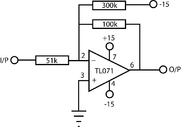
I think this is what you want. I've lifted this from Thomas Henry's Build a Better Music Synthesizer - it's from his CEM VCO design. He used it on the Triangle output (which is also 0-5v PP) to convert it to 10v PP centered around zero.
I haven't tested it, but in theory it should be fine.
BTW, I've just taken a look at the 4023 VCF PCB foil I posted... definitely the same version as I've used to build my own VCF's. I wish I could be more help - could you PM some high rez images of your board to me, I'll see what I can do.
Andy.
| Description: |
|
| Filesize: |
55.91 KB |
| Viewed: |
731 Time(s) |
| This image has been reduced to fit the page. Click on it to enlarge. |
|
_________________
Kronos 2-88, Kronos 61, Studiologic Sledge V2/SL, Broadwave ARP 2600EX, Broadwave 18U ARP based Eurorack Modular, Broadwave Minimoog Clone, GEM S2 Turbo.
Synth DIY Projects
Musical Doodlings |
|
|
Back to top
|
|
|
LetterBeacon
Joined: Mar 18, 2008
Posts: 454
Location: London, UK
|
| Posted: Thu Jan 08, 2009 8:36 am Post subject:
|
|
|
Andy, thanks so much for that! Being a bit of a beginner, I've had a hard time figuring out how to do that!
If I wanted to use that on the saw output (which is 0-6v), would it just be a case of changing the value of the 100K feedback resistor? |
|
|
Back to top
|
|
|
Broadwave
Joined: Feb 16, 2007
Posts: 347
Location: Manchester UK
Audio files: 6
|
| Posted: Thu Jan 08, 2009 8:51 am Post subject:
|
|
|
| LetterBeacon wrote: | | would it just be a case of changing the value of the 100K feedback resistor? |
Yes, I'd change the 100k resistor for a 51k and then follow it with a 50k trimmer to allow the voltage to be adjusted back down to 10v PP.
You may find that it's not *exactly* centered around zero, though it'll probably be fine for general use - otherwise I *think* you would need to change the value of the 300k resistor slightly.
_________________
Kronos 2-88, Kronos 61, Studiologic Sledge V2/SL, Broadwave ARP 2600EX, Broadwave 18U ARP based Eurorack Modular, Broadwave Minimoog Clone, GEM S2 Turbo.
Synth DIY Projects
Musical Doodlings |
|
|
Back to top
|
|
|
ericcoleridge
Joined: Jan 16, 2007
Posts: 889
Location: NYC
|
| Posted: Thu Jan 08, 2009 12:01 pm Post subject:
|
|
|
| AndyR1960 wrote: |
I think this is what you want. I've lifted this from Thomas Henry's Build a Better Music Synthesizer - it's from his CEM VCO design. He used it on the Triangle output (which is also 0-5v PP) to convert it to 10v PP centered around zero. |
Andy, you're the best!! I'll give this a shot tonight-- I'll post my findings.
| AndyR1960 wrote: |
BTW, I've just taken a look at the 4023 VCF PCB foil I posted... definitely the same version as I've used to build my own VCF's. I wish I could be more help - could you PM some high rez images of your board to me, I'll see what I can do.
|
I actually don't own a digtal camera, but as soon as I can borrow one, I'll take some pics and post them. Thanks for your help. |
|
|
Back to top
|
|
|
ericcoleridge
Joined: Jan 16, 2007
Posts: 889
Location: NYC
|
| Posted: Thu Jan 08, 2009 1:03 pm Post subject:
|
|
|
| LetterBeacon wrote: | Congratulations! Have you got any photos of the front panel? I'd be interested to see how you've laid it out.
|
I've got two of these boards etched, ones finished, the other still needs some assembly...
One is gonna get put together with an Arp Axxe MKI PCB (minus the VCF daughterboard) that I picked up on e-bay for $50. I'm gonna add a S+H section, a Yu-Synth Arp 4072 VCF, a mixer, maybe some other odds and ends, and essentially made an Arp 2600 reproduction. I've got some of the panel layed out in FPD with 30mm sliders. I have an Arp Solus, and I'm thinking of this project as a portable modular companion piece to my portable Solus. Both should be around the same size, and fit into the same size cases.
My second Dual Oddy VCO is gonna be the core of a Buchla 259 Programmable Complex Waveform Generator reproduction. I have a panel in FPD ready. The oddy VCOs will get coupled with a Serge style 3900 Norton Amp VC Saw to Tri/Sine waveshaper, a VC X-fader for low harmonic (Sine) to high harmonic (square) cross fading, and an Ian Fritz wavefolder for extreme VC Timbre modulation. there's also a Modulation Index, and all the other 259 sections. I have most everything done already.
i'll definitely try to get pictures up of all these projects as they materialize.
I really like this VCO. |
|
|
Back to top
|
|
|
numbertalk

Joined: May 05, 2008
Posts: 992
Location: Austin, TX
Audio files: 5
|
| Posted: Thu Jan 08, 2009 3:05 pm Post subject:
|
|
|
Hi Andy,
If I wanted to use ferrite beads for power supply filtering would I just replace the 2 jumpers for the main + & - voltages or would I also use one on the tap off of the + voltage that goes to the trace that hits the VCO 2 Freq multi-turn trimmer?
Thanks! |
|
|
Back to top
|
|
|
e-grad
Joined: Sep 12, 2008
Posts: 142
Location: Berlin
|
| Posted: Tue Jan 13, 2009 4:25 pm Post subject:
|
|
|
| Etaoin wrote: | | I used a 2k tempco with a parallel metal film 28.7k in my 4035. This gives you 1.87k with a tempco that should be close to that of the 2k tempco. |
Is *28K7* a typo? I think it should be rather 2K87 (or even 1K955)??
I'm new to this is and I could be totally wrong thus will appreciate any hint. |
|
|
Back to top
|
|
|
etaoin

Joined: Jun 30, 2005
Posts: 761
Location: Utrecht, NL
|
| Posted: Wed Jan 14, 2009 1:34 am Post subject:
|
|
|
No, it's not a typo.
I meant what I said: 28k7 MF parallel with 2k PTC. That gives you a resistance of 1 / ( 1/28.7 + 1/2 ) = 1.87k with a tempco close to that of the PTC (as the MF is stable).
Anything close to 2k (as you're suggesting) would almost halve the resistance.
_________________
http://www.casia.org/modular/ |
|
|
Back to top
|
|
|
Broadwave
Joined: Feb 16, 2007
Posts: 347
Location: Manchester UK
Audio files: 6
|
| Posted: Wed Jan 14, 2009 2:06 am Post subject:
|
|
|
| numbertalk wrote: | Hi Andy,
If I wanted to use ferrite beads for power supply filtering would I just replace the 2 jumpers for the main + & - voltages or would I also use one on the tap off of the + voltage that goes to the trace that hits the VCO 2 Freq multi-turn trimmer?
|
That would be fine... You could increase the value of the two smoothing caps which would also help, but I've had no problems leaving everything as it is.
Still working on remainder of the modules - LFO, Noise, S&H coming up soon.
_________________
Kronos 2-88, Kronos 61, Studiologic Sledge V2/SL, Broadwave ARP 2600EX, Broadwave 18U ARP based Eurorack Modular, Broadwave Minimoog Clone, GEM S2 Turbo.
Synth DIY Projects
Musical Doodlings |
|
|
Back to top
|
|
|
e-grad
Joined: Sep 12, 2008
Posts: 142
Location: Berlin
|
| Posted: Wed Jan 14, 2009 2:19 am Post subject:
|
|
|
| Etaoin wrote: | | No, it's not a typo. |
Thanks! |
|
|
Back to top
|
|
|
LetterBeacon
Joined: Mar 18, 2008
Posts: 454
Location: London, UK
|
| Posted: Wed Jan 14, 2009 3:03 am Post subject:
|
|
|
| AndyR1960 wrote: | | Still working on remainder of the modules - LFO, Noise, S&H coming up soon. |
Looking forward to them - an ARP modular will be mine, oh yes, it will be mine!! |
|
|
Back to top
|
|
|
pdman1
Joined: Mar 28, 2007
Posts: 50
Location: North Shore Massachusetts
|
| Posted: Thu Jan 15, 2009 11:31 am Post subject:
|
|
|
is there any chance that ready made PCBs for the Oscillator will become available?
kep up the good work! |
|
|
Back to top
|
|
|
LetterBeacon
Joined: Mar 18, 2008
Posts: 454
Location: London, UK
|
| Posted: Thu Jan 15, 2009 11:49 am Post subject:
|
|
|
| Looks like Magic Smoke are working on a design as we speak... |
|
|
Back to top
|
|
|
funkyfarm
Joined: Jan 21, 2007
Posts: 583
Location: France
Audio files: 3
|
|
|
Back to top
|
|
|
numbertalk
Joined: May 05, 2008
Posts: 992
Location: Austin, TX
Audio files: 5
|
|
|
Back to top
|
|
|
funkyfarm
Joined: Jan 21, 2007
Posts: 583
Location: France
Audio files: 3
|
| Posted: Sun Jan 18, 2009 11:08 pm Post subject:
|
|
|
The schematic above shows us vco1 (master) syncs vco2 (slave).
 |
|
|
Back to top
|
|
|
numbertalk
Joined: May 05, 2008
Posts: 992
Location: Austin, TX
Audio files: 5
|
| Posted: Sun Jan 18, 2009 11:15 pm Post subject:
|
|
|
| funkyfarm wrote: | The schematic above shows us vco1 (master) syncs vco2 (slave).
|
Thanks - that's what I thought - just not sure which is which on the PCB. |
|
|
Back to top
|
|
|
funkyfarm
Joined: Jan 21, 2007
Posts: 583
Location: France
Audio files: 3
|
|
|
Back to top
|
|
|
numbertalk
Joined: May 05, 2008
Posts: 992
Location: Austin, TX
Audio files: 5
|
| Posted: Sun Jan 18, 2009 11:37 pm Post subject:
|
|
|
Thank you!
One more question I can't quite figure out from the schematic and Andy's layout - which throw is the switch flipped to for sync to be active? As it is on Andy's diagram - http://electro-music.com/forum/phpbb-files/arp_odyssey_dual_vco_126.pdf - as he has that switch illustrated here, the switch right now is connected to the lower throw (which connects the pole of the switch to a jumper leading to a 100K resistor and then a 2N3904 transistor etc..., while the other "upper" throw is connected to the negative voltage rail through a 100K resistor). Which throw activates the sync connection? In the schematic the sync switch simply has an "off" throw which connects to the positive voltage, so this seems different than what I'm seeing on Andy's layout.
Thanks again. |
|
|
Back to top
|
|
|
Broadwave
Joined: Feb 16, 2007
Posts: 347
Location: Manchester UK
Audio files: 6
|
| Posted: Mon Jan 19, 2009 2:04 am Post subject:
|
|
|
| numbertalk wrote: | In the schematic the sync switch simply has an "off" throw which connects to the positive voltage, so this seems different than what I'm seeing on Andy's layout.
Thanks again. |
The schematic above is for the Mk 1 VCO (although there's not much difference soundwise) my layout is from the Mk 2/3.
VCO 2 provides the sync signal, and as shown on my layout, sync occurs when the switch toggle is down. In the "up" position the sync input to VCO 1 is tied to -15v via a 100k resistor, which prevents any spurious re-triggering.
_________________
Kronos 2-88, Kronos 61, Studiologic Sledge V2/SL, Broadwave ARP 2600EX, Broadwave 18U ARP based Eurorack Modular, Broadwave Minimoog Clone, GEM S2 Turbo.
Synth DIY Projects
Musical Doodlings |
|
|
Back to top
|
|
|
|

 Forum index » DIY Hardware and Software