| Author |
Message |
numbertalk

Joined: May 05, 2008
Posts: 992
Location: Austin, TX
Audio files: 5
|
 Posted: Tue Jul 08, 2008 12:05 pm Post subject:
wasp vcf questions Posted: Tue Jul 08, 2008 12:05 pm Post subject:
wasp vcf questions |
  |
|
I've built several effects pedals and have decided to move onto my first synth project, which I've decided is going to be the JH Wasp VCF clone (http://modular.fonik.de/pdf/Wasp%20Filter%20clone.pdf). I have a few questions about this project. Some of these are things I just haven't encountered yet while building effects stompboxes.
1) What kind of jacks are the 3 that mount to the PCB with 4 terminals? Anyone have a Mouser part #?
2) To connect the 3 pots to the board, these are just 3 pin MTA connectors (.1" female cable mount Mouser part AMP 6404413 & .1" Male PCB mount Mouser part AMP 6404563), right?
3) What about the 16-pin connection in the bottom right - looks like the power connection? I tried looking on the data sheet for the 3 pin .1" MTA connectors for a 16 pin version but didn't see any - anyone have part numbers for the male and female connectors this requires?
4) If I wanted to power this project with 2 batteries while I'm building and testing, how would I wire it to the power connection? Is this possible? Guess this is part of why I'm confused with this connection having 16 pins - from the other modules I've looked at so far only 3 pins seem to be needed (one for + voltage, one for 0V and the third for - voltage).
5) Are P1 & P3 linear taper?
Thanks. I'm really looking forward to getting started building a synth. |
|
|
Back to top
|
|
 |
jhaible
Joined: May 25, 2007
Posts: 2014
Location: Germany
Audio files: 24
|
| Posted: Tue Jul 08, 2008 4:06 pm Post subject:
Re: wasp vcf questions |
|
|
| numbertalk wrote: | I've built several effects pedals and have decided to move onto my first synth project, which I've decided is going to be the JH Wasp VCF clone (http://modular.fonik.de/pdf/Wasp%20Filter%20clone.pdf). I have a few questions about this project. Some of these are things I just haven't encountered yet while building effects stompboxes.
1) What kind of jacks are the 3 that mount to the PCB with 4 terminals? Anyone have a Mouser part #?
2) To connect the 3 pots to the board, these are just 3 pin MTA connectors (.1" female cable mount Mouser part AMP 6404413 & .1" Male PCB mount Mouser part AMP 6404563), right?
3) What about the 16-pin connection in the bottom right - looks like the power connection? I tried looking on the data sheet for the 3 pin .1" MTA connectors for a 16 pin version but didn't see any - anyone have part numbers for the male and female connectors this requires?
4) If I wanted to power this project with 2 batteries while I'm building and testing, how would I wire it to the power connection? Is this possible? Guess this is part of why I'm confused with this connection having 16 pins - from the other modules I've looked at so far only 3 pins seem to be needed (one for + voltage, one for 0V and the third for - voltage).
5) Are P1 & P3 linear taper?
Thanks. I'm really looking forward to getting started building a synth. |

I'm not aware I've ever made a PCB, or suggested connectors for this ...
JH.
_________________
"I tell you the truth, if anyone says to this mountain, 'Go, throw yourself into the sea,' and does not doubt in his heart but believes that what he says will happen, it will be done for him. Therefore I tell you, whatever you ask for in prayer, believe that you have received it, and it will be yours." (Mk 11,23f) |
|
|
Back to top
|
|
|
numbertalk
Joined: May 05, 2008
Posts: 992
Location: Austin, TX
Audio files: 5
|
| Posted: Tue Jul 08, 2008 6:47 pm Post subject:
Re: wasp vcf questions |
|
|
Well, I guess this topic needs to be moved somewhere else then. The person who did create this PCB and spec, which I did include a link to in my posting, mentions his spec is based on your design (the documentation at the link I sent even has your name at the top). So, maybe I wasn't clear, but I wasn't suggesting you had ever made a PCB or suggested connectors for this module. Rather, I posted this topic here because I thought/hoped that the person who did adapt your design (or someone who has built this specific version of this module) might read this forum and might be able to help me out.
Anyway, I think I've figured most of it out. I found dual row 16 pin connectors but not at Mouser or anywhere else I usually order from. Not sure about the panel mount jacks that would connect correctly to this specific PCB either but based on that specific schematic it looks like each jack only actually connects to the circuit in 2 places, so it doesn't seem like they'd be switched or too difficult for me to work out how to wire up with solder lug mono jacks.
| jhaible wrote: | | numbertalk wrote: | I've built several effects pedals and have decided to move onto my first synth project, which I've decided is going to be the JH Wasp VCF clone (http://modular.fonik.de/pdf/Wasp%20Filter%20clone.pdf). I have a few questions about this project. Some of these are things I just haven't encountered yet while building effects stompboxes.
1) What kind of jacks are the 3 that mount to the PCB with 4 terminals? Anyone have a Mouser part #?
2) To connect the 3 pots to the board, these are just 3 pin MTA connectors (.1" female cable mount Mouser part AMP 6404413 & .1" Male PCB mount Mouser part AMP 6404563), right?
3) What about the 16-pin connection in the bottom right - looks like the power connection? I tried looking on the data sheet for the 3 pin .1" MTA connectors for a 16 pin version but didn't see any - anyone have part numbers for the male and female connectors this requires?
4) If I wanted to power this project with 2 batteries while I'm building and testing, how would I wire it to the power connection? Is this possible? Guess this is part of why I'm confused with this connection having 16 pins - from the other modules I've looked at so far only 3 pins seem to be needed (one for + voltage, one for 0V and the third for - voltage).
5) Are P1 & P3 linear taper?
Thanks. I'm really looking forward to getting started building a synth. |
I'm not aware I've ever made a PCB, or suggested connectors for this ...
JH. |
|
|
|
Back to top
|
|
|
jhaible
Joined: May 25, 2007
Posts: 2014
Location: Germany
Audio files: 24
|
| Posted: Tue Jul 08, 2008 10:49 pm Post subject:
Re: wasp vcf questions |
|
|
| numbertalk wrote: | | Well, I guess this topic needs to be moved somewhere else then. The person who did create this PCB and spec, which I did include a link to in my posting, mentions his spec is based on your design (the documentation at the link I sent even has your name at the top). So, maybe I wasn't clear, but I wasn't suggesting you had ever made a PCB or suggested connectors for this module. Rather, I posted this topic here because I thought/hoped that the person who did adapt your design (or someone who has built this specific version of this module) might read this forum and might be able to help me out. |
I see.
JH.
_________________
"I tell you the truth, if anyone says to this mountain, 'Go, throw yourself into the sea,' and does not doubt in his heart but believes that what he says will happen, it will be done for him. Therefore I tell you, whatever you ask for in prayer, believe that you have received it, and it will be yours." (Mk 11,23f) |
|
|
Back to top
|
|
|
Fetafarmer
Joined: Jul 29, 2007
Posts: 32
|
| Posted: Wed Jul 09, 2008 4:01 am Post subject:
Re: wasp vcf questions |
|
|
| numbertalk wrote: | I've built several effects pedals and have decided to move onto my first synth project, which I've decided is going to be the JH Wasp VCF clone (http://modular.fonik.de/pdf/Wasp%20Filter%20clone.pdf). I have a few questions about this project. Some of these are things I just haven't encountered yet while building effects stompboxes.
|
Hi numbertalk. One thing you should consider is that you're not going to get a very exciting response from the filter without some kind of dynamic control: an envelope generator or follower, an LFO, etc. Jürgen did create a simple ADSR/LFO specifically for his Wasp design, and you'd probably want to build that, as well. I'm sure the schematic can be found on his website.
Another consideration for you is the probable difference in signal levels used/expected by this module vs. those of your effects pedals. This filter is probably optimized for 10V p-p, while your stompboxes probably deal with less than 2V p-p. In this case, a level shifting circuit, such as the CGS Stompbox Adapter, would be helpful.
| Quote: |
2) To connect the 3 pots to the board, these are just 3 pin MTA connectors (.1" female cable mount Mouser part AMP 6404413 & .1" Male PCB mount Mouser part AMP 6404563), right?
|
You can use .100" headers, or just wire straight to the PCB itself. I use the Molex KK series myself (Mouser 538-22-23-2031 for example).
| Quote: |
3) What about the 16-pin connection in the bottom right - looks like the power connection? I tried looking on the data sheet for the 3 pin .1" MTA connectors for a 16 pin version but didn't see any - anyone have part numbers for the male and female connectors this requires?
|
You don't need 16 pins at all. This circuit runs on a single supply, +5V (which the 7805 converts down from +15V), so you really only need two pins: one supplying +15V, and one for ground. The other connections to ground at that header can be wired to any pots or jacks that need a path to ground.
Cheers,
Kevin |
|
|
Back to top
|
|
|
fonik

Joined: Jun 07, 2006
Posts: 3950
Location: Germany
Audio files: 23
|
| Posted: Wed Jul 09, 2008 5:42 am Post subject:
Re: wasp vcf questions |
|
|
| numbertalk wrote: | I've built several effects pedals and have decided to move onto my first synth project, which I've decided is going to be the JH Wasp VCF clone (http://modular.fonik.de/pdf/Wasp%20Filter%20clone.pdf). I have a few questions about this project. Some of these are things I just haven't encountered yet while building effects stompboxes.
1) What kind of jacks are the 3 that mount to the PCB with 4 terminals? Anyone have a Mouser part #?
|
most of your questions seem to have been answered already.
i made the PCB layout you're refereing to for my own purposes. the tracks are wide enough for press'n'peel blue process.
so what about the sockets? i use cliff sockets to mount the PCB to the front panel. they are not available from mouser.
the power connector is a ribbon connector as used by i.e. doepfer.
you can easily power the filter from a 9V cell. i tried this circuit with up to 15V. no problem at all. one of my favorite filters. i am currently working on a 2nd clone.
hope that helps.
_________________

cheers,
matthias
____________
Big Boss at fonitronik
Tech Buddy at Random*Source |
|
|
Back to top
|
|
|
numbertalk
Joined: May 05, 2008
Posts: 992
Location: Austin, TX
Audio files: 5
|
| Posted: Wed Jul 09, 2008 6:42 am Post subject:
Re: wasp vcf questions |
|
|
Thanks for all the information! I actually do own some synth equipment - an MS50, MS20 and also a Moogerfooger CP251, so I do have some EG and modulation sources. Just to start building, before I have enough modules to stand alone, I plan to use them with my MS50.
It sounds like I don't need the 16 pin connectors but Fonik, just out of curiosity, where do you get those Doepfer connectors, because I looked online, on their website and at Analogue Haven (U.S. Doepfer dealer) but I couldn't find any part #s or places to get them.
One more question:
| Quote: | | you really only need two pins: one supplying +15V, and one for ground |
So just to check that I know how to do this (though it sounds like I could use just a single 9V battery), I could wire 2 9V batteries together like so: the positive connector from one battery goes to the +15V pin on the board, the negative of that battery as well as the positive of the 2nd battery both connect to the ground pin and then though the - voltage isn't used, the negative lead of the 2nd battery can be connected to the -15V pin. Would that be right? Basically something like this:
positive pin <battery> 0V pin <battery> negative pin
Thanks again.
| Fetafarmer wrote: | | numbertalk wrote: | I've built several effects pedals and have decided to move onto my first synth project, which I've decided is going to be the JH Wasp VCF clone (http://modular.fonik.de/pdf/Wasp%20Filter%20clone.pdf). I have a few questions about this project. Some of these are things I just haven't encountered yet while building effects stompboxes.
|
Hi numbertalk. One thing you should consider is that you're not going to get a very exciting response from the filter without some kind of dynamic control: an envelope generator or follower, an LFO, etc. Jürgen did create a simple ADSR/LFO specifically for his Wasp design, and you'd probably want to build that, as well. I'm sure the schematic can be found on his website.
Another consideration for you is the probable difference in signal levels used/expected by this module vs. those of your effects pedals. This filter is probably optimized for 10V p-p, while your stompboxes probably deal with less than 2V p-p. In this case, a level shifting circuit, such as the CGS Stompbox Adapter, would be helpful.
| Quote: |
2) To connect the 3 pots to the board, these are just 3 pin MTA connectors (.1" female cable mount Mouser part AMP 6404413 & .1" Male PCB mount Mouser part AMP 6404563), right?
|
You can use .100" headers, or just wire straight to the PCB itself. I use the Molex KK series myself (Mouser 538-22-23-2031 for example).
| Quote: |
3) What about the 16-pin connection in the bottom right - looks like the power connection? I tried looking on the data sheet for the 3 pin .1" MTA connectors for a 16 pin version but didn't see any - anyone have part numbers for the male and female connectors this requires?
|
You don't need 16 pins at all. This circuit runs on a single supply, +5V (which the 7805 converts down from +15V), so you really only need two pins: one supplying +15V, and one for ground. The other connections to ground at that header can be wired to any pots or jacks that need a path to ground.
Cheers,
Kevin |
|
|
|
Back to top
|
|
|
fonik
Joined: Jun 07, 2006
Posts: 3950
Location: Germany
Audio files: 23
|
| Posted: Wed Jul 09, 2008 8:18 am Post subject:
Re: wasp vcf questions |
|
|
| numbertalk wrote: | | It sounds like I don't need the 16 pin connectors but Fonik, just out of curiosity, where do you get those Doepfer connectors, because I looked online, on their website and at Analogue Haven (U.S. Doepfer dealer) but I couldn't find any part #s or places to get them. |
over here (in germany) you'll get them from almost any electronic components seller, they are quite common in europe.
| Quote: | So just to check that I know how to do this (though it sounds like I could use just a single 9V battery), I could wire 2 9V batteries together like so: the positive connector from one battery goes to the +15V pin on the board, the negative of that battery as well as the positive of the 2nd battery both connect to the ground pin and then though the - voltage isn't used, the negative lead of the 2nd battery can be connected to the -15V pin. Would that be right? Basically something like this:
positive pin <battery> 0V pin <battery> negative pin
Thanks again.
|
no need to do this. the module does not require a bipolar PSU. just connect one 9V cell: +pin of cell to +V of PCB and -pin of cell to GND.
you could even ignore the 5V regulator (install a jumper for the positive rail instead) and power the module from 9V.
_________________
cheers,
matthias
____________
Big Boss at fonitronik
Tech Buddy at Random*Source |
|
|
Back to top
|
|
|
numbertalk
Joined: May 05, 2008
Posts: 992
Location: Austin, TX
Audio files: 5
|
| Posted: Wed Jul 09, 2008 9:20 am Post subject:
Re: wasp vcf questions |
|
|
So instead of the LM7805 I would put a jumper from where pin 1 to where pin 3 of the LM7805 would have been (crossing over but not connecting the ground line)?
Also, you mention on your web site that in the documentation P3 (potentiometer for resonance control) is accidentally reversed - just making sure this is still the case and that I should reverse the wiring for this one.
Thanks!
| fonik wrote: | | numbertalk wrote: | | It sounds like I don't need the 16 pin connectors but Fonik, just out of curiosity, where do you get those Doepfer connectors, because I looked online, on their website and at Analogue Haven (U.S. Doepfer dealer) but I couldn't find any part #s or places to get them. |
over here (in germany) you'll get them from almost any electronic components seller, they are quite common in europe.
| Quote: | So just to check that I know how to do this (though it sounds like I could use just a single 9V battery), I could wire 2 9V batteries together like so: the positive connector from one battery goes to the +15V pin on the board, the negative of that battery as well as the positive of the 2nd battery both connect to the ground pin and then though the - voltage isn't used, the negative lead of the 2nd battery can be connected to the -15V pin. Would that be right? Basically something like this:
positive pin <battery> 0V pin <battery> negative pin
Thanks again.
|
no need to do this. the module does not require a bipolar PSU. just connect one 9V cell: +pin of cell to +V of PCB and -pin of cell to GND.
you could even ignore the 5V regulator (install a jumper for the positive rail instead) and power the module from 9V. |
|
|
|
Back to top
|
|
|
numbertalk
Joined: May 05, 2008
Posts: 992
Location: Austin, TX
Audio files: 5
|
| Posted: Wed Jul 09, 2008 10:13 am Post subject:
Re: wasp vcf questions |
|
|
Also curious, what's the part # for the Cliff Sockets you use? Is it the S1?
| fonik wrote: | | numbertalk wrote: | | It sounds like I don't need the 16 pin connectors but Fonik, just out of curiosity, where do you get those Doepfer connectors, because I looked online, on their website and at Analogue Haven (U.S. Doepfer dealer) but I couldn't find any part #s or places to get them. |
over here (in germany) you'll get them from almost any electronic components seller, they are quite common in europe.
| Quote: | So just to check that I know how to do this (though it sounds like I could use just a single 9V battery), I could wire 2 9V batteries together like so: the positive connector from one battery goes to the +15V pin on the board, the negative of that battery as well as the positive of the 2nd battery both connect to the ground pin and then though the - voltage isn't used, the negative lead of the 2nd battery can be connected to the -15V pin. Would that be right? Basically something like this:
positive pin <battery> 0V pin <battery> negative pin
Thanks again.
|
no need to do this. the module does not require a bipolar PSU. just connect one 9V cell: +pin of cell to +V of PCB and -pin of cell to GND.
you could even ignore the 5V regulator (install a jumper for the positive rail instead) and power the module from 9V. |
|
|
|
Back to top
|
|
|
fonik
Joined: Jun 07, 2006
Posts: 3950
Location: Germany
Audio files: 23
|
| Posted: Wed Jul 09, 2008 11:45 am Post subject:
Re: wasp vcf questions |
|
|
| numbertalk wrote: | | So instead of the LM7805 I would put a jumper from where pin 1 to where pin 3 of the LM7805 would have been (crossing over but not connecting the ground line)? |
yep!
| Quote: | | Also, you mention on your web site that in the documentation P3 (potentiometer for resonance control) is accidentally reversed - just making sure this is still the case and that I should reverse the wiring for this one. |
it is still the case. 
_________________
cheers,
matthias
____________
Big Boss at fonitronik
Tech Buddy at Random*Source |
|
|
Back to top
|
|
|
numbertalk
Joined: May 05, 2008
Posts: 992
Location: Austin, TX
Audio files: 5
|
| Posted: Wed Jul 09, 2008 11:47 am Post subject:
Re: wasp vcf questions |
|
|
Great, thanks again for all the help. Think I'm good to go.
| fonik wrote: | | numbertalk wrote: | | So instead of the LM7805 I would put a jumper from where pin 1 to where pin 3 of the LM7805 would have been (crossing over but not connecting the ground line)? |
yep!
| Quote: | | Also, you mention on your web site that in the documentation P3 (potentiometer for resonance control) is accidentally reversed - just making sure this is still the case and that I should reverse the wiring for this one. |
it is still the case. |
|
|
|
Back to top
|
|
|
fonik
Joined: Jun 07, 2006
Posts: 3950
Location: Germany
Audio files: 23
|
| Posted: Wed Jul 09, 2008 11:55 am Post subject:
Re: wasp vcf questions |
|
|
| numbertalk wrote: | | Also curious, what's the part # for the Cliff Sockets you use? Is it the S1? |
i use the CL1384(1). this would be the part number to the cliff catalogue. you will get them from farnell, i guess, and/or from cliff directly.
this is the socket most of the modular systems in euro or frakrack format use, IIRC.
_________________
cheers,
matthias
____________
Big Boss at fonitronik
Tech Buddy at Random*Source |
|
|
Back to top
|
|
|
numbertalk
Joined: May 05, 2008
Posts: 992
Location: Austin, TX
Audio files: 5
|
| Posted: Wed Jul 09, 2008 12:49 pm Post subject:
Re: wasp vcf questions |
|
|
Thanks again. Looks like these aren't readily available in the states.
| fonik wrote: | | numbertalk wrote: | | Also curious, what's the part # for the Cliff Sockets you use? Is it the S1? |
i use the CL1384(1). this would be the part number to the cliff catalogue. you will get them from farnell, i guess, and/or from cliff directly.
this is the socket most of the modular systems in euro or frakrack format use, IIRC. |
|
|
|
Back to top
|
|
|
fonik
Joined: Jun 07, 2006
Posts: 3950
Location: Germany
Audio files: 23
|
|
|
Back to top
|
|
|
numbertalk
Joined: May 05, 2008
Posts: 992
Location: Austin, TX
Audio files: 5
|
| Posted: Wed Jul 09, 2008 6:29 pm Post subject:
|
|
|
Ah, I didn't realize I could get them directly from Cliff - I'll get in touch with them. Thanks again.
|
|
|
Back to top
|
|
|
fonik
Joined: Jun 07, 2006
Posts: 3950
Location: Germany
Audio files: 23
|
| Posted: Thu Jul 10, 2008 2:31 am Post subject:
|
|
|
| numbertalk wrote: | Ah, I didn't realize I could get them directly from Cliff - I'll get in touch with them. Thanks again.
|
good luck.
farnell stocks the version with solder lugs only (CL1382).
_________________
cheers,
matthias
____________
Big Boss at fonitronik
Tech Buddy at Random*Source |
|
|
Back to top
|
|
|
numbertalk
Joined: May 05, 2008
Posts: 992
Location: Austin, TX
Audio files: 5
|
| Posted: Tue Aug 05, 2008 3:16 pm Post subject:
|
|
|
| EDIT - Fixed it! Was a bum chip. Works and sounds fantastic. |
|
|
Back to top
|
|
|
moosapotamus

Joined: May 11, 2007
Posts: 113
Location: New Hampshire USA
|
| Posted: Mon Aug 18, 2008 7:01 am Post subject:
|
|
|
I know that in the Wasp circuit the distortion section is intentionally located after the filter. But, would it be worth adding one additional switch to also have the option of switching the distortion before the filter (pre or post distortion)? Or rather, just replace the distortion toggle with a rotary switch wired up to give pre/off/post settings for the distortion? And maybe also make the feedback resistance (R24) variable to adjust the amount of distortion?
Or, maybe I should just breadboard it and find out for myself?! 
~ Charlie
_________________
moosapotamus.net
"I tend to like anything that I think sounds good" |
|
|
Back to top
|
|
|
fonik
Joined: Jun 07, 2006
Posts: 3950
Location: Germany
Audio files: 23
|
| Posted: Tue Aug 19, 2008 2:26 pm Post subject:
|
|
|
| moosapotamus wrote: | I know that in the Wasp circuit the distortion section is intentionally located after the filter. But, would it be worth adding one additional switch to also have the option of switching the distortion before the filter (pre or post distortion)? Or rather, just replace the distortion toggle with a rotary switch wired up to give pre/off/post settings for the distortion? And maybe also make the feedback resistance (R24) variable to adjust the amount of distortion?
Or, maybe I should just breadboard it and find out for myself?!
~ Charlie |
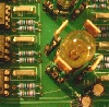
what i did was to bring the distortions in and out to the frontpanel (but it is normalized using switching sockets). i build a three stage distortion circuit (seb francis box-o-trix cmos distortion circuit) and added a switch to select the number of stages. the IC is getting fairly hot, but not hotter than 60°C. finally i added a simple wet/dry mix and brought the inputs and the output to the panel, too:

_________________
cheers,
matthias
____________
Big Boss at fonitronik
Tech Buddy at Random*Source |
|
|
Back to top
|
|
|
moosapotamus
Joined: May 11, 2007
Posts: 113
Location: New Hampshire USA
|
| Posted: Wed Aug 20, 2008 5:24 am Post subject:
|
|
|
That looks pretty cool, fonik.
So if you want, you can patch the distortion either before or after the filter?
What's the normal/krank switch do?
~ Charlie
_________________
moosapotamus.net
"I tend to like anything that I think sounds good" |
|
|
Back to top
|
|
|
fonik
Joined: Jun 07, 2006
Posts: 3950
Location: Germany
Audio files: 23
|
| Posted: Wed Aug 20, 2008 5:41 am Post subject:
|
|
|
| moosapotamus wrote: | That looks pretty cool, fonik.
So if you want, you can patch the distortion either before or after the filter? |
sure
not that've used the filter much yet. i still have to tweak the cutoff control (i implemented an expo control, not the linear one, which makes juergens clone unique...
| Quote: | What's the normal/krank switch do?
~ Charlie |
the krank/normal control switches the diodes in the resonnance feedback path. you choose between 1n4148 (normal) and green LEDs (krank) which increase the clipping.
_________________
cheers,
matthias
____________
Big Boss at fonitronik
Tech Buddy at Random*Source |
|
|
Back to top
|
|
|
moosapotamus
Joined: May 11, 2007
Posts: 113
Location: New Hampshire USA
|
| Posted: Wed Aug 20, 2008 1:00 pm Post subject:
|
|
|

~ Charlie
_________________
moosapotamus.net
"I tend to like anything that I think sounds good" |
|
|
Back to top
|
|
|
|

 Forum index » DIY Hardware and Software » Jürgen Haible designs
