| Author |
Message |
ianbax
Joined: Apr 20, 2022
Posts: 42
Location: Sheffield, UK
|
 Posted: Wed Apr 20, 2022 2:27 pm Post subject:
Variable Pulse Width with Vactrol Control Posted: Wed Apr 20, 2022 2:27 pm Post subject:
Variable Pulse Width with Vactrol Control
Subject description: Trying to apply vactrol control to 3 legged pot |
  |
|
Hi,
I'm just starting my lunetta journey, well, restarting actually, after a long time with my head in code I've gone back to hardware and finally getting round to making a 'modular' lunetta setup.
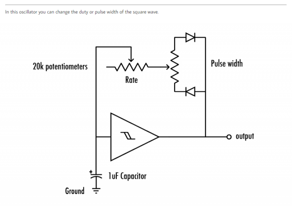
I've got a 4093 square wave going with variable duty cycle based on two diodes and a pot. I've put the schematics I've copied and followed the discussion here https://electro-music.com/forum/topic-47266.html
I've found the modulation of the pulse width gives some more interest to the sound and I'd like to automate it - with other variable resistor controlled parameters (e.g. pitch of an oscillator) I've replaced the pot with a homemade vactrol - i.e. an LDR flashed by an LED linked to a lower frequency oscillator - a but I'm a bit stumped how to get this to work when all three legs of a pot are connected, as a divider rather than variable resistor. I thought I could just bridge one side of the pot with a LDR but it doesn't work to effect pulse width, instead the pitch is altered.
Grateful for any advice!
| Description: |
|
| Filesize: |
80.25 KB |
| Viewed: |
184 Time(s) |
| This image has been reduced to fit the page. Click on it to enlarge. |

|
| Description: |
| Duty cycle circuit copied |
|
| Filesize: |
41.85 KB |
| Viewed: |
204 Time(s) |
| This image has been reduced to fit the page. Click on it to enlarge. |
|
|
|
|
Back to top
|
|
 |
blue hell
Site Admin

Joined: Apr 03, 2004
Posts: 24505
Location: The Netherlands, Enschede
Audio files: 298
G2 patch files: 320
|
Posted: Wed Apr 20, 2022 7:12 pm Post subject:
Re: Variable Pulse Width with Vactrol Control
Subject description: Trying to apply vactrol control to 3 legged pot |
|
|
| ianbax wrote: | | Grateful for any advice! |
Hi ianbax and 
Let me try the 'any advice' then ... or the first thought i had (without thinking :') )
A pot really is like two resistors where the one is the reciprocal of the other, so .. I'd expect two LDRs.
To make that reciprocally controled by a PWM signal there should be two shiners too .. LEDs . where the one gets the inverse PWM control from the other.
Does that make sense for you?
Edit: on a 2nd thought - as the LDR / LED system is not linear and you may still get frequency control .. so .. eh .. maybe the first thought was just stupid 
Edit 2 : 'stupid' just means 'naive' here - or 'without thinking', of course :`) anyway - it is an interesting problem!
_________________
Jan
also .. could someone please turn down the thermostat a bit.
 |
|
|
Back to top
|
|
|
ianbax
Joined: Apr 20, 2022
Posts: 42
Location: Sheffield, UK
|
| Posted: Thu Apr 21, 2022 1:10 am Post subject:
|
|
|
Thanks.
I think I see what might be happening then - the circuit works best for me when the frequency pot and width pot are the same value (100k) - the large resistance of the LDR (could be about 1M fully dark) must be too large and means you get a frequency change rather than an effect on duty cycle.
Is there a way to modify the circuit to just control 'one side' of the the pulse width - with the two diodes-pot setup you can go between 0-100% (about 2-98% with a limiting resistor) but really 0-50% and 50-100% sounds the same in terms of the modulation effect. If it were possible to just to one side with a pot in variable resistor configuration, then the LDR across the resistor trick might work for me. I've done a bit of trial and error but turned up nothing.
Otherwise perhaps I need to investigate voltage control of some kind. I'd sort of resisted that as it seems to stray away from the simplicity of the lunetta idea and into bipolar power supplies, op amps and 'proper' synth circuits. |
|
|
Back to top
|
|
|
Ruebezahl

Joined: Mar 09, 2014
Posts: 112
Location: Taiwan
Audio files: 4
|
| Posted: Thu Apr 21, 2022 1:24 am Post subject:
|
|
|
Like blue hell said, if you want to emulate the behaviour of a voltage divider potentiometer, you would really have to replace both sides with a vactrol, where as one LED is the inverted version of the other one. You could achieve that with one of the other gates of the 4093, if it's only a squarewave control signal.
But what i would suggest is replacing one of the resistors (or potentiometer wings) with a vactrol and playing around with a resistor size of the other one. I am actually sure this way you will find something that sounds interesting enough.
This approach is for example used to replace volume knobs (that are voltage dividers to ground) with LDRs, i also used this technique making a LDR controlled Logic Gate.
Let me know if you need a schematic of it...
_________________
https://soundcloud.com/ruebezahl |
|
|
Back to top
|
|
|
synaesthesia

Joined: May 27, 2014
Posts: 291
Location: Germany
Audio files: 85
|
| Posted: Thu Apr 21, 2022 7:22 am Post subject:
|
|
|
| Agree to "...sure this way you will find something that sounds interesting enough." When you are only looking for the audible result, then consider that a PWM of 80/20 sounds exactly the same as a PWM of 20/80. So you can use a 100k pot (or vactrol) in one diode path and a 100k fixed resistor in the other, for example. |
|
|
Back to top
|
|
|
ianbax
Joined: Apr 20, 2022
Posts: 42
Location: Sheffield, UK
|
| Posted: Thu Apr 21, 2022 8:09 am Post subject:
|
|
|
Thanks for all the replies - so I split the 100k width pot into two 47k pots (which I had to hand, I guess 50k would be an exact swap out) and then fixed one at max and turned the other - and as you've said 50-100 (or there about) is the same sonically as 0-50 you get that strange modulating effect. I guess one of the pots could actually be a fixed resistor - but I can't find anything close in my selection pack right now.
It's difficult to replace the pot directly with a vactrol because the range of the LDR (~1M I think) is too great but placed across the 47k pot you get the parallel resistance so the overall range isn't as wide but you still get some nice modulation especially at fast blink speeds. Unless there's a way to set the range of an LDR?
As someone said up thread the non-linear nature of the LDR means you don't get that smooth modulation but I've got another circuit in the works which gradually fades the LED in and out rather than blinking on and off, so I'm hoping to get a more gradual effect in my finished vactrols. |
|
|
Back to top
|
|
|
Ruebezahl
Joined: Mar 09, 2014
Posts: 112
Location: Taiwan
Audio files: 4
|
| Posted: Fri Apr 22, 2022 1:32 am Post subject:
|
|
|
Regarding setting the range of an LDR, you can either try to find different LDRs, or perhaps combine them with regular resistors either in series or paralel (or both  ). This trick you can also use to get the right value fixed resistors if you don't happen to have them. ). This trick you can also use to get the right value fixed resistors if you don't happen to have them.
Also you can try using a bigger resistor in front of the LED, or using different color LED.
The LDRs i mostly use have around 150k when i cover them completely.
edit: ah, sorry, i see you already have the paralell resistance, since you keep the pot.
well, one thought i have is why you don't try to put a much bigger potentiometer on the other side? i didn't try this circuit, but i would suppose the size of the potentiometer doesn't matter too much, since it is just a voltage divider in the end, and what matters is the ratio of both sides.
_________________
https://soundcloud.com/ruebezahl |
|
|
Back to top
|
|
|
ianbax
Joined: Apr 20, 2022
Posts: 42
Location: Sheffield, UK
|
| Posted: Fri Apr 22, 2022 1:55 am Post subject:
|
|
|
| Ruebezahl wrote: | Regarding setting the range of an LDR, you can either try to find different LDRs, or perhaps combine them with regular resistors either in series or paralel (or both ). This trick you can also use to get the right value fixed resistors if you don't happen to have them.
Also you can try using a bigger resistor in front of the LED, or using different color LED.
The LDRs i mostly use have around 150k when i cover them completely.
edit: ah, sorry, i see you already have the paralell resistance, since you keep the pot.
well, one thought i have is why you don't try to put a much bigger potentiometer on the other side? i didn't try this circuit, but i would suppose the size of the potentiometer doesn't matter too much, since it is just a voltage divider in the end, and what matters is the ratio of both sides. |
No need to apologise - thanks for the tips. I think I'm going to keep experimenting with values. Looking at my LDR order I can see there's several in their catalogue with different ranges - IIRC I chose one with a large dark resistance because I was making the LDR-tremolo circuit from the Nicolas Collins book and wanted to guarantee it cutting the signal. That's where the thing with vactrols started....
For some reason in this circuit it works best for modulation with the frequency pot and width pot roughly equal (I used 100k in the non LDR version) - I've grasped the basics of the Schmitt trigger oscillator but if I'm truly honest I'm not sure quite how the two different facing diodes are working. But using my ears and a scope I can see it *is* working.
I've just seen PHOBOs' XOR based width circuit too where you input two copies of the same wave but with one slowed down (with a low pass filter?), so I might try that, as it only requires a variable resistor. |
|
|
Back to top
|
|
|
synaesthesia
Joined: May 27, 2014
Posts: 291
Location: Germany
Audio files: 85
|
| Posted: Fri Apr 22, 2022 4:33 am Post subject:
|
|
|
| Regarding choice of LDR: my best experience is with the GL5528 types if you want to control (well, as far as that is possible) their resistance via an LED. I have had good results with orange LEDs plus PWM getting an almost linear response from a few K to a few hundered K Ohms. When using LDRs for Low-Pass Gates, the GL5516 types are much better and have a longer decay. |
|
|
Back to top
|
|
|
ianbax
Joined: Apr 20, 2022
Posts: 42
Location: Sheffield, UK
|
| Posted: Fri Nov 18, 2022 6:43 am Post subject:
|
|
|
Resurrecting an old thread.
I had success with my home made vactrols and fading LED circuit to make a crude sort of 'VCA' with attack-hold-decay envelope for my lunetta (In the process realising why proper synths use voltage control! but you know, it's all about the learning and journey sometimes).
I thought I'd try and make something more controllable using an Arduino lighting the LED to different brightnesses via one of its PWM pins but I ran into a problem - the PWM frequency becomes audible as a sort of tremelo or AM type effect at high duty cycles. The LDR is evidently detecting the on/off pattern of the LDR and producing an oscillating resistance.
synaesthesia you mentioned getting good results with PWM - what was the source? Did you smooth it out? I've been reading about using R-C filters to do that. Or does the narrow range of LDR you recommend (5528) do some smoothing? |
|
|
Back to top
|
|
|
Grumble
Joined: Nov 23, 2015
Posts: 1319
Location: Netherlands
Audio files: 30
|
| Posted: Sat Nov 19, 2022 3:19 pm Post subject:
|
|
|
Start with a triangle-wave or saw-wave oscillator and feed that in a comparator where the other voltage is controlled by a vactrol.
Job done 🤓👍🏻
_________________
my synth |
|
|
Back to top
|
|
|
|

 Forum index » DIY Hardware and Software » Lunettas - circuits inspired by Stanley Lunetta
