| Author |
Message |
ianbax
Joined: Apr 20, 2022
Posts: 42
Location: Sheffield, UK
|
 Posted: Tue Sep 26, 2023 8:25 am Post subject:
Noise in Lunetta system Posted: Tue Sep 26, 2023 8:25 am Post subject:
Noise in Lunetta system
Subject description: White - and other colours - noise module |
  |
|
I've been looking at making a noise module which will suit my lunetta's digital nature not the traditional sample and hold random voltages kind.
One constraint is I'm working at 5v single sided supply, so I've gone for digital noise generated by a LFSR - I could roll my own but I've got hold of one of Electric Druid's noise chips which doesn't repeat for 60 years or something crazy.
My plan is to extract random bits from this chip (using a CD4094 shift register with latch I think) which can be made available at patch points then drive triggers or the binary inputs to a 4051 to select random notes say.
But on to my question ! I was looking at filtering the noise to other colours. I'll probably have these available as audio output but I was wondering if there was any value in routing them to the shift register - random gates circuit. I know in traditional noise modules like the Source of Uncertainty, the colour of the source noise is important to the distribution of voltages it produces. Will it make any (noticeable) difference to the gate pattern produced if different coloured noises are used? I'm not sure how to simulate it. |
|
|
Back to top
|
|
 |
zaphod betamax
Joined: Nov 27, 2020
Posts: 62
Location: sarnia
|
|
|
Back to top
|
|
|
ianbax
Joined: Apr 20, 2022
Posts: 42
Location: Sheffield, UK
|
| Posted: Thu Oct 05, 2023 4:02 am Post subject:
|
|
|
Thanks - I'll take a look. I didn't think it was possible to get transistor noise with just 5v (all the circuits I've seen online are 12v).
Does brown noise make difference to the gating?
Interesting about the 4094 - I was having a play this week and the strobe pin doesn't work as I thought it might. I've introduced some d flip flops (40174) to capture the random 0s and 1s at set intervals.
I might be over complicating things but having fun. |
|
|
Back to top
|
|
|
zaphod betamax
Joined: Nov 27, 2020
Posts: 62
Location: sarnia
|
| Posted: Thu Oct 05, 2023 4:40 am Post subject:
|
|
|
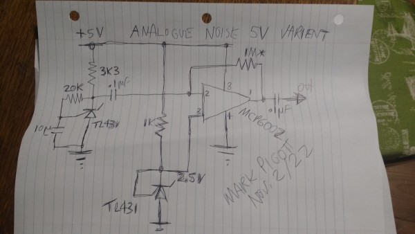
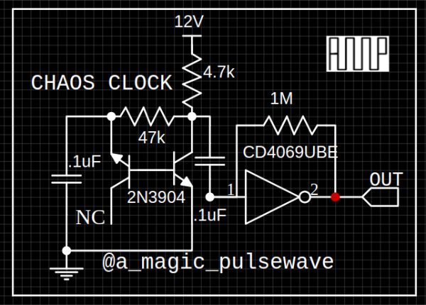
This circuit works fine all the time at 5V, it might even work at 3.3, but I never tried.
To simplifiy you can use a 10k,10k voltage divider on pin 3 of the op am and it works fine as well.
This triggers shift registers fine as it is biased near the trigger point.
| ianbax wrote: | Thanks - I'll take a look. I didn't think it was possible to get transistor noise with just 5v (all the circuits I've seen online are 12v).
Does brown noise make difference to the gating?
Interesting about the 4094 - I was having a play this week and the strobe pin doesn't work as I thought it might. I've introduced some d flip flops (40174) to capture the random 0s and 1s at set intervals.
I might be over complicating things but having fun. |
|
|
|
Back to top
|
|
|
zaphod betamax
Joined: Nov 27, 2020
Posts: 62
Location: sarnia
|
|
|
Back to top
|
|
|
zaphod betamax
Joined: Nov 27, 2020
Posts: 62
Location: sarnia
|
| Posted: Sun Nov 12, 2023 9:13 am Post subject:
|
|
|
I find the LFSR a whole lot of chips that can be done analog with just some caps, resistors a TL431 and a MCP6002.
Analog brown noise has enough random to trigger a CD4517BE. |
|
|
Back to top
|
|
|
Top Top

Joined: Feb 02, 2010
Posts: 266
Location: California
|
|
|
Back to top
|
|
|
zaphod betamax
Joined: Nov 27, 2020
Posts: 62
Location: sarnia
|
Posted: Wed Jul 17, 2024 6:41 am Post subject:
Re: Noise in Lunetta system
Subject description: White - and other colours - noise module |
|
|
May I suggest the CD4517BE rather than the CD4094.
In my 3 years of using these as S&H they sound more musical
than the ramdomality of the CD4094 in my opinion.
My 4094s sit unused whilst I have a dozen 4517s standing by!
| ianbax wrote: | I've been looking at making a noise module which will suit my lunetta's digital nature not the traditional sample and hold random voltages kind.
One constraint is I'm working at 5v single sided supply, so I've gone for digital noise generated by a LFSR - I could roll my own but I've got hold of one of Electric Druid's noise chips which doesn't repeat for 60 years or something crazy.
My plan is to extract random bits from this chip (using a CD4094 shift register with latch I think) which can be made available at patch points then drive triggers or the binary inputs to a 4051 to select random notes say.
But on to my question ! I was looking at filtering the noise to other colours. I'll probably have these available as audio output but I was wondering if there was any value in routing them to the shift register - random gates circuit. I know in traditional noise modules like the Source of Uncertainty, the colour of the source noise is important to the distribution of voltages it produces. Will it make any (noticeable) difference to the gate pattern produced if different coloured noises are used? I'm not sure how to simulate it. |
|
|
|
Back to top
|
|
|
|

 Forum index » DIY Hardware and Software » Lunettas - circuits inspired by Stanley Lunetta