| Author |
Message |
tjookum

Joined: May 25, 2010
Posts: 360
Location: Netherlands
Audio files: 26
|
 Posted: Sat Aug 04, 2012 1:12 pm Post subject: Posted: Sat Aug 04, 2012 1:12 pm Post subject:
|
  |
|
Totally awesome! I really like the idea of a wearable lunetta band, Stanley Lunetta must be proud.
I can totally recommend the slacker melodygenerator as a good next project. But really the best thing to do is to get a breadboard and experiment. Build a few circuits, get familiar with the cmos ic's and the lunetta way of thinking and just go from there.
Maybe this might work well as a hat?
http://www.youtube.com/watch?v=AXO6gzsD6xo
_________________
There he goes. One of God's own prototypes. A high-powered mutant of some kind never even considered for mass production. Too weird to live, and too rare to die.
Hunter S. Thompson
movies
noise |
|
|
Back to top
|
|
 |
Draal

Joined: May 18, 2010
Posts: 308
Location: Oak Park, IL
Audio files: 5
|
| Posted: Sun Aug 05, 2012 5:33 am Post subject:
|
|
|
You've brought my Sid And Marty Krofft nightmares to life. I will never be the same again! You're H.R. Puffnsynth 
Keep up the great work!
_________________
Zontar Prevails! |
|
|
Back to top
|
|
|
Tomoroh Hidari
Joined: May 04, 2012
Posts: 39
Location: Vienna
Audio files: 2
|
| Posted: Tue Aug 07, 2012 10:42 am Post subject:
|
|
|
wow, finally made it trhough this thread!
very helpful and inspirational. thanks!
so far i've tried a few lunetta circuits on breadboard... working on getting something built...
found an old joystick and working on building a quad 40106 osc in it.
two oscs controlled by the x+y axis of the joystick (both 100k slide-potis), two oscs by two pots I plan to place in the space of two pusbuttons and vol. by a third (allready built-in) pot...
i'm thinking of using the pushbuttons on the joystick (2) for the following -
1 switches off the gating of oscs 2+4 by 1+3 (yeah, that's part of the plan too)
2 switches off audio-out
since these are normal off switches, though, i'll have to do the switching via 4066s and inverters, though, which I yet have to figure out fully how to.
any ideas/criticism/peer-review?
cheers, th
_________________
~~~
http://blog.ivorybunker.com/
http://tomoroh.ivorybunker.com/
http://tomorohhidari.bandcamp.com |
|
|
Back to top
|
|
|
PHOBoS

Joined: Jan 14, 2010
Posts: 5881
Location: Moon Base
Audio files: 709
|
|
|
Back to top
|
|
|
tjookum
Joined: May 25, 2010
Posts: 360
Location: Netherlands
Audio files: 26
|
|
|
Back to top
|
|
|
elmegil

Joined: Mar 20, 2012
Posts: 2179
Location: Chicago
Audio files: 16
|
| Posted: Sat Oct 06, 2012 8:14 pm Post subject:
|
|
|
| I see it has to be a particular model of 4069...any idea if it works with other forms of inverters (dual connected NANDs, things with Schmitt Triggers in them?) |
|
|
Back to top
|
|
|
tjookum
Joined: May 25, 2010
Posts: 360
Location: Netherlands
Audio files: 26
|
| Posted: Sun Oct 07, 2012 1:32 am Post subject:
|
|
|
I've only seen 4069 and 4049 being used in linear applications, I don't think other cmos ic's will work.
My entire experience with cmos is based on trial and error, maybe some of the other forum members is willing to explain why it has to be the 4069UBE?
_________________
There he goes. One of God's own prototypes. A high-powered mutant of some kind never even considered for mass production. Too weird to live, and too rare to die.
Hunter S. Thompson
movies
noise |
|
|
Back to top
|
|
|
Psyingo

Joined: Jun 11, 2009
Posts: 248
Location: Canada
|
| Posted: Sun Oct 07, 2012 8:10 am Post subject:
|
|
|
you can use any non-buffered (and depending on the situation, buffered) non-schmitt trigger inverting logic for linear operation. that means 4001, 4011, 4009 etc. of course you can also use the 'building block' ic the 4007.
4001 and 4011 are pretty interchangeable when i was building analog drums i swapped between the 4011 and 4001 with no problem.
maybe this would be of help understanding the difference:
http://www.ti.com/lit/an/scha004/scha004.pdf
basically buffered has extra inverters buffering somewhere in the circuit, where as unbuffered has just the gate. so for a 4011 buffered will have the NAND gate and some buffering on the input or output, depending on the manufacturer. an unbuffered 4011 will only have the NAND.
that TI link is an interesting read, i would suggest it if you want to get serious about this stuff.. |
|
|
Back to top
|
|
|
elmegil
Joined: Mar 20, 2012
Posts: 2179
Location: Chicago
Audio files: 16
|
| Posted: Sun Oct 07, 2012 8:44 am Post subject:
|
|
|
| Cool, thank you for the reference. |
|
|
Back to top
|
|
|
RingMad

Joined: Jan 15, 2011
Posts: 429
Location: Montreal, Canada
Audio files: 4
|
|
|
Back to top
|
|
|
Psyingo
Joined: Jun 11, 2009
Posts: 248
Location: Canada
|
| Posted: Sat Oct 13, 2012 8:38 am Post subject:
|
|
|
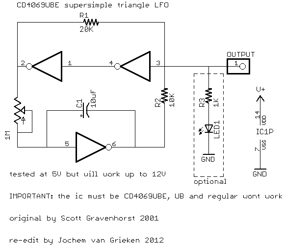
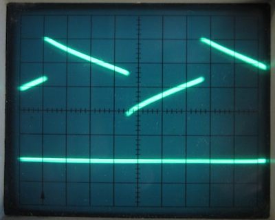
| RingMad wrote: | I'm not exactly a beginner any more, but with this famous 4069 circuit, I feel like one. I've tried to build it several times. Now I finally got some actual CD4069UBE's, but they don't seem to work any better than the particular model I had before. I built the circuit exactly as in the one posted above by tjookum. The triangle is not smooth, there are glitches where the wave falls or rises vertically, which is audible as a click at lower frequencies.
In the scope shot below, the bottom horizontal trace is just to show where the actual ground is (notice the approx. +3.5 V DC offset!).
Ultimately, I'm looking for a cheap (low-parts count) triangular very LFO I can feed some "vactrols" (opto-isolators) with.
James. |
Tjookums schematic is meant for 5 volt operation.you will need to tweak values for different supplies. I have schematic for 12v and 9v somewhere if you'd like. |
|
|
Back to top
|
|
|
RingMad
Joined: Jan 15, 2011
Posts: 429
Location: Montreal, Canada
Audio files: 4
|
| Posted: Sat Oct 13, 2012 6:38 pm Post subject:
|
|
|
| Psyingo wrote: | | Tjookums schematic is meant for 5 volt operation.you will need to tweak values for different supplies. I have schematic for 12v and 9v somewhere if you'd like. |
Oh yes, 9V please. I forgot to mention that's what I was using. The schematic did say it will work up to 12V.
James. |
|
|
Back to top
|
|
|
Psyingo
Joined: Jun 11, 2009
Posts: 248
Location: Canada
|
| Posted: Sat Oct 13, 2012 7:10 pm Post subject:
|
|
|
| well, it does 'work' but not the way it should. |
|
|
Back to top
|
|
|
Psyingo
Joined: Jun 11, 2009
Posts: 248
Location: Canada
|
| Posted: Sat Oct 13, 2012 7:50 pm Post subject:
|
|
|

heres the 9v one, or 12v. R8 may need to be adjusted a bit. but its pretty good as is.
the output will never quite be rail to rail, it'll always float above ground and below +v. you would have to remove the offset and run it into an amp to get it to be full swing.
if you want this to be an LFO C1 should be larger. |
|
|
Back to top
|
|
|
tjookum
Joined: May 25, 2010
Posts: 360
Location: Netherlands
Audio files: 26
|
| Posted: Sun Oct 14, 2012 2:38 pm Post subject:
|
|
|
Thank you psyingo for providing a lot of additional info.
I did notice in my limited experiments that the R8 and R9 resistance ratio is crucial when working with different voltages. That's why I altered the original by scott gravenhorst to my preferred 5v.
And thanks RingMad, I think that scope image shows very clearly the problem some are having with this circuit. I've used it on several drone type circuits and I've discovered it's very hard to make a pure triangle wave with linear cmos. But as everything wich involves the lunetta way of thinking, I considder it a feature  . .
I hope psyingo's schematic works for you(and others who need it at 9v).
_________________
There he goes. One of God's own prototypes. A high-powered mutant of some kind never even considered for mass production. Too weird to live, and too rare to die.
Hunter S. Thompson
movies
noise |
|
|
Back to top
|
|
|
RingMad
Joined: Jan 15, 2011
Posts: 429
Location: Montreal, Canada
Audio files: 4
|
| Posted: Sun Oct 14, 2012 5:26 pm Post subject:
|
|
|
Thanks a lot, Psyingo! I finally get a nice triangle out of the 4069 on 9V!
This also works quite well as a VLFO (Very Low Frequency Oscillator). With an approx. 4700uF cap in there, I get around 17 minutes per cycle (approx. 0.001 Hz), which is what I was aiming for! And it's quite smooth. With a bit of DC shifting, this should work quite well for my application.
James. |
|
|
Back to top
|
|
|
Psyingo
Joined: Jun 11, 2009
Posts: 248
Location: Canada
|
| Posted: Sun Oct 14, 2012 5:39 pm Post subject:
|
|
|
| Nice.glad it worked. And yeah it handles low frequency pretty well |
|
|
Back to top
|
|
|
Musica_En_Fuego

Joined: Jun 19, 2018
Posts: 24
Location: New Castle, Delaware, USA
|
Posted: Fri Jul 20, 2018 6:41 pm Post subject:
Fiddling with the 4040 + 555 to make some crazy noise.
Subject description: Making weird noise. |
|
|
After building my goto 555 timer toy organ from the Forrest Mims mini engineer's book and looking at stomczak's pinout for the 4040. I mixed the two to make some unusual noise. After a bit of poking around, I managed to make some interesting sounds.
https://photos.app.goo.gl/aGPdvk2xBbKXcK5c8
https://photos.app.goo.gl/L6aVN2KpiW2sE3uo7 |
|
|
Back to top
|
|
|
Steveg

Joined: Apr 23, 2015
Posts: 184
Location: Perth, Australia
|
| Posted: Fri Jul 20, 2018 7:23 pm Post subject:
|
|
|
Welcome, great job there!
You'll find plenty of extra audible bling here! |
|
|
Back to top
|
|
|
JovianPyx

Joined: Nov 20, 2007
Posts: 1988
Location: West Red Spot, Jupiter
Audio files: 224
|
| Posted: Sun Jul 22, 2018 1:06 pm Post subject:
|
|
|
| tjookum wrote: | I've only seen 4069 and 4049 being used in linear applications, I don't think other cmos ic's will work.
My entire experience with cmos is based on trial and error, maybe some of the other forum members is willing to explain why it has to be the 4069UBE? |
4069UB and UBE work better because of the internal construction of the chip. The buffered version has 3 inverters in series per gate where the UB gates are just one inverter structure. Each inverter is a pair of CMOS transistors. Look at the datasheets for both B and UB versions and you'll see this.
In the case of the buffered ones, the gain of the circuit when the input is at (Vdd-Vss)/2 is extremely high which improves noise immunity and increases the switching speed. The extra gain makes using it as a linear amplifier more touchy.
As for why the triangle doesn't have perfectly straight ramps like an opamp would have, it is mainly because even the unbuffered (UB) chips exhibit highest gain when the input is (Vdd-Vss)/2. It isn't nearly as bad as the buffered ones though.
When I first did this circuit for my Fatman, I saw this effect on my oscope, but I didn't care and liked the fact that it's slightly curved instead of dead straight. The ramp is actually a spline shape. This can actually be abused a bit more to make a waveform something like a sine, though also not perfect. Using some simple linear amplifiers to "waveshape" the LFO would exaggerate the spline curve effect to the degree that the point can be made to almost disappear into a curved top/bottom like a sine.
_________________
FPGA, dsPIC and Fatman Synth Stuff
Time flies like a banana.
Fruit flies when you're having fun.
BTW, Do these genes make my ass look fat?
corruptio optimi pessima
|
|
|
Back to top
|
|
|
dadinfinitum
Joined: Dec 16, 2019
Posts: 41
Location: Maryland, US
|
|
|
Back to top
|
|
|
Sven
Joined: Mar 10, 2017
Posts: 53
Location: Norway
|
| Posted: Thu Aug 29, 2024 8:38 am Post subject:
|
|
|
Hello,
the schematic by tjookum is not the same as the one from Scott Gravenhorst which can be found here http://scott.joviansynth.com/electronics/4069_lfo.gif
You will find that the 100k resistor is misplaced. You should also tie the unused outputs to ground. |
|
|
Back to top
|
|
|
blue hell
Site Admin

Joined: Apr 03, 2004
Posts: 24504
Location: The Netherlands, Enschede
Audio files: 298
G2 patch files: 320
|
| Posted: Thu Aug 29, 2024 9:01 am Post subject:
|
|
|
| Sven wrote: | | You should also tie the unused outputs to ground. |
Make that inputs ...
_________________
Jan
also .. could someone please turn down the thermostat a bit.
 |
|
|
Back to top
|
|
|
Sven
Joined: Mar 10, 2017
Posts: 53
Location: Norway
|
| Posted: Thu Aug 29, 2024 12:19 pm Post subject:
|
|
|
| blue hell wrote: | | Sven wrote: | | You should also tie the unused outputs to ground. |
Make that inputs ... |
Yes you are absulutely correct!  |
|
|
Back to top
|
|
|
|

 Forum index » DIY Hardware and Software » Lunettas - circuits inspired by Stanley Lunetta