| Author |
Message |
tehskull
Joined: May 07, 2011
Posts: 23
Location: Kentucky
Audio files: 1
|
 Posted: Wed Jul 13, 2011 4:46 pm Post subject: Posted: Wed Jul 13, 2011 4:46 pm Post subject:
|
  |
|
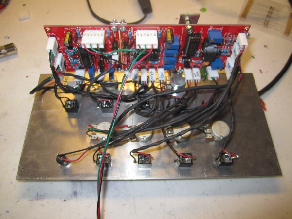
Finished mine last night. Working on calibrating it now. I have only been doing DIY synths for about 3 months. This is my 4th completed module. Calibrating is going OK so far. When the VCO gets into higher octaves, it cuts off. Powering it off then on brings it back once the frequency is turned back down. Not sure if this is a characteristic of my 4046 or not (which is a motorola). The HF trimpot is set to maximum resistance per Thomas's calibration instructions. I am going to continue calibrating with tools now. However if anyone has any input it would be gratetfully appreciated. So far I am very happy with it. A very big thanks to Matthias and Thomas for this great project.
Thanks!
Andrew
| Description: |
|
| Filesize: |
2.94 MB |
| Viewed: |
475 Time(s) |
| This image has been reduced to fit the page. Click on it to enlarge. |
|
| Description: |
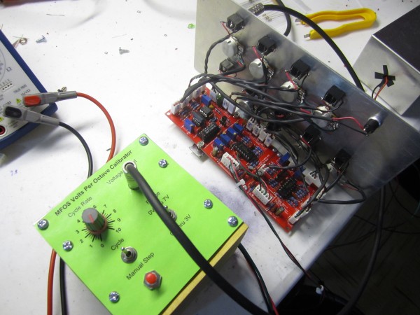
| Completed X-4046 VCO & MFOS 1v\oct calibrator |
|
| Filesize: |
2.6 MB |
| Viewed: |
469 Time(s) |
| This image has been reduced to fit the page. Click on it to enlarge. |
|
|
|
|
Back to top
|
|
 |
fonik

Joined: Jun 07, 2006
Posts: 3950
Location: Germany
Audio files: 23
|
| Posted: Wed Jul 13, 2011 11:43 pm Post subject:
|
|
|
| Bogus Noise wrote: | I'd be up for buying a couple of these PCBs as well if you do another run.  |
i still have spares! so how many sets do you need?
_________________

cheers,
matthias
____________
Big Boss at fonitronik
Tech Buddy at Random*Source |
|
|
Back to top
|
|
|
Bogus Noise
Joined: Jun 03, 2009
Posts: 65
Location: Sheffield
|
| Posted: Thu Jul 14, 2011 12:23 am Post subject:
|
|
|
| Ah, nice one! Sending a reply to your PM now. |
|
|
Back to top
|
|
|
fonik
Joined: Jun 07, 2006
Posts: 3950
Location: Germany
Audio files: 23
|
| Posted: Thu Jul 14, 2011 1:40 am Post subject:
|
|
|
| tehskull wrote: | | Calibrating is going OK so far. When the VCO gets into higher octaves, it cuts off. Powering it off then on brings it back once the frequency is turned back down. Not sure if this is a characteristic of my 4046 or not (which is a motorola). |
mmmh. maybe you could post this in the thomas henry sub-forum? someone might have experienced this earlier, if it is related to the 4046...
_________________
cheers,
matthias
____________
Big Boss at fonitronik
Tech Buddy at Random*Source |
|
|
Back to top
|
|
|
loopcycle

Joined: Nov 06, 2006
Posts: 101
Location: California
|
| Posted: Thu Jul 14, 2011 3:53 pm Post subject:
|
|
|
ive built one now and am finding myself here because i could not tune 1v/O whatsoever.
i now see that the ON semiconductor 4046 was a fail and that's what ive got in it now.
i also have the nxp 4046 and will be installing it tonight to see if my results improve.
other than the tracking problems (about a semitone per two octaves), im enjoying the sound of this oscillator.
the "pips" in the triangle wave make it buzzier than others in my system,
but the osc FMs wonderfully and has a very wide range, well down into lfo territory.
edit:
problem #1: 100k in R2...changed that to 390R
i then swapped out the ON PLL for the NXP PLL--wow, what a difference.
it was remarkable how much my waveform improved. i can barely see the pips in the triangle now
its calibrated very well now and it sounds fantastic. cant wait to build the next one
 |
|
|
Back to top
|
|
|
fonik
Joined: Jun 07, 2006
Posts: 3950
Location: Germany
Audio files: 23
|
| Posted: Fri Jul 15, 2011 12:51 pm Post subject:
|
|
|
sorry about the trouble due to the error in the BOM.
all the more i am happy that you are happy now! tried the hardsync? it blew me away...
_________________
cheers,
matthias
____________
Big Boss at fonitronik
Tech Buddy at Random*Source |
|
|
Back to top
|
|
|
loopcycle
Joined: Nov 06, 2006
Posts: 101
Location: California
|
| Posted: Fri Jul 15, 2011 1:28 pm Post subject:
|
|
|
| fonik wrote: | sorry about the trouble due to the error in the BOM.
all the more i am happy that you are happy now! tried the hardsync? it blew me away... |
no problem, was an easy fix =)
and yes, that hardsync is about the hardest ive heard.
its sound competes well with my 5pulser!
thanks again matthias for making these pcbs available, and many thanks to thomas henry for the badass vco |
|
|
Back to top
|
|
|
tehskull
Joined: May 07, 2011
Posts: 23
Location: Kentucky
Audio files: 1
|
| Posted: Fri Jul 15, 2011 6:10 pm Post subject:
|
|
|
| After swapping my 4046 for an NXP and a few hours of messing about with the trim pots, it is working beautifully! Sounds fantastic with my MFOS 10 step sequencer. The only thing that I do not understand is how to use the hard sync. Everyone says it sounds great so I am dying to hear it myself. Do you need 2 VCO's connected with this? Or does the CV connect to it? Or am i completely wrong lol? |
|
|
Back to top
|
|
|
emdot_ambient
Joined: Nov 22, 2009
Posts: 667
Location: Frederick, MD
|
| Posted: Fri Jul 15, 2011 7:47 pm Post subject:
|
|
|
You have to run an audio input (usually a wave from another VCO) into the Sync In jack. Basically you're turning this VCO into a slave and the external VCO into a master (as far as pitch goes). The master VCO restarts the period of the slave VCO, forcing it to have the same base frequency of the master.
Detuning the slave will create different timbres while maintaining technical pitch unity.
_________________
Looking for a certain ratio since 1978 |
|
|
Back to top
|
|
|
fonik
Joined: Jun 07, 2006
Posts: 3950
Location: Germany
Audio files: 23
|
| Posted: Sat Jul 16, 2011 2:41 am Post subject:
|
|
|
| tehskull wrote: | | After swapping my 4046 for an NXP and a few hours of messing about with the trim pots, it is working beautifully! Sounds fantastic with my MFOS 10 step sequencer. The only thing that I do not understand is how to use the hard sync. Everyone says it sounds great so I am dying to hear it myself. Do you need 2 VCO's connected with this? Or does the CV connect to it? Or am i completely wrong lol? |
geat to hear it's working now.
so this certain motorola had an issue, or would you have had this issue with any motorola from the same batch? would be an interesting information for scott. the NXP is what i am using...
_________________
cheers,
matthias
____________
Big Boss at fonitronik
Tech Buddy at Random*Source |
|
|
Back to top
|
|
|
kupfer_m
Joined: Oct 14, 2010
Posts: 48
Location: Belgium
|
| Posted: Sat Jul 16, 2011 3:01 am Post subject:
|
|
|
Hi,
What's the reason for the DC/AC switch for the LinFM input?
When would one use AC and when DC?
Thanks,
Jim |
|
|
Back to top
|
|
|
fonik
Joined: Jun 07, 2006
Posts: 3950
Location: Germany
Audio files: 23
|
| Posted: Sat Jul 16, 2011 3:33 am Post subject:
|
|
|
| kupfer_m wrote: | Hi,
What's the reason for the DC/AC switch for the LinFM input?
When would one use AC and when DC?
Thanks,
Jim |
i think this queston is related to modular synthesis i general, not to this VCO only.
how i understand it (however, my knowledge on these things is not THAT profound):
AC coupled input would remove DC offset, thus not influencing the root frequency of the 4046 VCO that much.
just try it.
_________________
cheers,
matthias
____________
Big Boss at fonitronik
Tech Buddy at Random*Source |
|
|
Back to top
|
|
|
emdot_ambient
Joined: Nov 22, 2009
Posts: 667
Location: Frederick, MD
|
| Posted: Sat Jul 16, 2011 3:51 am Post subject:
|
|
|
| fonik wrote: | | kupfer_m wrote: | | What's the reason for the DC/AC switch for the LinFM input? |
AC coupled input would remove DC offset, thus not influencing the root frequency of the 4046 VCO that much.
just try it. |
Or, in another example, if you ran a bi-polar LFO wave (say, a -5V to +5V triangle wave) into a mixer and added +5V DC offset, the resulting wave would go from 0 to +10V, but +5V of that is a DC offset.
If you jacked that into the Lin FM of this VCO and set the switch to AC, the AC coupling (if I understand this correctly) would strip out the +5V DC and leave you once again with a bi-polar modulation source. If that's the case, then you probably don't want that because the negative going part of the modulation source would have no effect on the FM (since this is not a Through Zero VCO).
Flip the switch to DC and the entire signal would go through, making the full spectrum of the modulation source available.
Again...if my understanding is correct!
_________________
Looking for a certain ratio since 1978 |
|
|
Back to top
|
|
|
tokyomatik

Joined: Jan 20, 2011
Posts: 171
Location: berlin
Audio files: 6
|
| Posted: Thu Jul 21, 2011 7:28 am Post subject:
|
|
|
hi mattias
i have a question about the skew function
i don't understand if it's possible to make it cv controllable
on the pcbs i was checking the in and outs
so i have
triangle
rampoid with his skew control
saw
sine
and pulse
but i don't see in wich way i could modulate the skew
just adding a connection from the tip of a jack to the middle pin (pin2) of the potentiometer could work? |
|
|
Back to top
|
|
|
fonik
Joined: Jun 07, 2006
Posts: 3950
Location: Germany
Audio files: 23
|
| Posted: Thu Jul 21, 2011 7:35 am Post subject:
|
|
|
| tokyomatik wrote: | hi mattias
i have a question about the skew function
i don't understand if it's possible to make it cv controllable
on the pcbs i was checking the in and outs
so i have
triangle
rampoid with his skew control
saw
sine
and pulse
but i don't see in wich way i could modulate the skew
just adding a connection from the tip of a jack to the middle pin (pin2) of the potentiometer could work? |
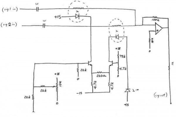
if you take a look at the schematic you will see how it works:
from the VCO core we have the saw and the saw outputs. they are simply mixed manually with a potentiometer (saw and tri on the CW/CCW, mix on the wiper), and buffered with an opamp (voltage follower). actually not mixed, but faded into each other.
therefor the waveshaper PCB provides the saw and a tri input.
to have voltage control you would need at least two VCA circuits, however, you could do it with two vactrols.
_________________
cheers,
matthias
____________
Big Boss at fonitronik
Tech Buddy at Random*Source |
|
|
Back to top
|
|
|
tokyomatik
Joined: Jan 20, 2011
Posts: 171
Location: berlin
Audio files: 6
|
| Posted: Thu Jul 21, 2011 4:25 pm Post subject:
|
|
|
vactrols?...it sounds interesting....
but really i don't know where to start..... 
why 2 vactrols?
1 for the triangle input & the other for the saw input? i'm already lost... 
let me try....(i did something similar to my voice of saturn....)
so, if i connect the positve of the vactrol to the tip of the jack, and the negative to the ground
and then i go to the potentiometer?...mhhh 
somebody can give some tips....
so sad that an interesting function like modulating the skew is not already on board like for example the xr2206 vco....
peace |
|
|
Back to top
|
|
|
rosch

Joined: Oct 03, 2009
Posts: 164
Location: germany
|
| Posted: Thu Jul 21, 2011 5:30 pm Post subject:
|
|
|
the vactrol is a vc resistor. so the ldr part would do the job of the pot, while it's controlled by a cv applied to the led side of the vactrol.
i've seen an example of a voltage divider somewhere around here in a thread not so long ago. that explained quite well how to use a vactrol. |
|
|
Back to top
|
|
|
hop.sing
Joined: Jun 11, 2011
Posts: 8
Location: Germany
Audio files: 1
|
|
|
Back to top
|
|
|
fonik
Joined: Jun 07, 2006
Posts: 3950
Location: Germany
Audio files: 23
|
| Posted: Fri Jul 22, 2011 2:50 am Post subject:
|
|
|
that's what i was thinking of (buchla/mark verbos?). i recently ordered some H11F3 optocouplers, which are much cheaper than vactrol. i hopefully will be able to adapt the above ciruit easily...
_________________
cheers,
matthias
____________
Big Boss at fonitronik
Tech Buddy at Random*Source |
|
|
Back to top
|
|
|
rosch
Joined: Oct 03, 2009
Posts: 164
Location: germany
|
| Posted: Fri Jul 22, 2011 3:53 am Post subject:
|
|
|
| fonik wrote: | | that's what i was thinking of (buchla/mark verbos?). i recently ordered some H11F3 optocouplers, which are much cheaper than vactrol. i hopefully will be able to adapt the above ciruit easily... |
 looking forward for that!! looking forward for that!! |
|
|
Back to top
|
|
|
hop.sing
Joined: Jun 11, 2011
Posts: 8
Location: Germany
Audio files: 1
|
| Posted: Fri Jul 22, 2011 6:40 am Post subject:
|
|
|
| Quote: | | i hopefully will be able to adapt the above ciruit easily... |
Well, one could build a little standalone module with the above circuit and use it to crossfade the triangle and saw outputs of the x-4046.
It would be usefulf for many different tasks anyway.
And is probably very easy to build, even on veroboard.
Tobias |
|
|
Back to top
|
|
|
tokyomatik
Joined: Jan 20, 2011
Posts: 171
Location: berlin
Audio files: 6
|
| Posted: Sat Jul 23, 2011 5:11 pm Post subject:
|
|
|
| fonik wrote: | | that's what i was thinking of (buchla/mark verbos?). i recently ordered some H11F3 optocouplers, which are much cheaper than vactrol. i hopefully will be able to adapt the above ciruit easily... |
keep us updated
that could be a really nice addition to the x-4046
 |
|
|
Back to top
|
|
|
tokyomatik
Joined: Jan 20, 2011
Posts: 171
Location: berlin
Audio files: 6
|
Posted: Mon Jul 25, 2011 9:34 pm Post subject:
 |
|
|
ok forget about modulate the skew...for now
i have more basic problems with the modules
i almost finished the first one, all the pots connected and just 1v/oct + the triangle output.... for a first test should be enough....(??) usually when i have at least sound coming out then i feel more motivated to mount all the rest 
but i don't have a 2k tempco right now
so i did maybe something strange, replacing it with a 2 metallic resistors
1k each 1%
and connected the triangle output to hear a sound to see if it works but
nothing....not even a beep!
for the ics i have a nxp HEF4046, i also tried a fairchild but nothing changed
q1 q2 is a LM394....
uffff
ok...where should i start to see what is wrong? |
|
|
Back to top
|
|
|
fonik
Joined: Jun 07, 2006
Posts: 3950
Location: Germany
Audio files: 23
|
| Posted: Mon Jul 25, 2011 11:24 pm Post subject:
|
|
|
check to see if you have any signal on pins 4, 6, and 7 of the 4046.
check power on all ICs
check wiring
_________________
cheers,
matthias
____________
Big Boss at fonitronik
Tech Buddy at Random*Source |
|
|
Back to top
|
|
|
tokyomatik
Joined: Jan 20, 2011
Posts: 171
Location: berlin
Audio files: 6
|
| Posted: Tue Jul 26, 2011 6:55 am Post subject:
|
|
|
hhmmm
so i checked the power at pin 8 & 9 of the 4046
i have 9.47v..... i'm powering my system with +/-12v
if i remove the 2 metallic resistors that i used to replace the 2k tempco
the value change to 9.27v... |
|
|
Back to top
|
|
|
|

 Forum index » DIY Hardware and Software » fonik's place