| Author |
Message |
elmegil

Joined: Mar 20, 2012
Posts: 2179
Location: Chicago
Audio files: 16
|
 Posted: Mon Oct 30, 2017 6:05 pm Post subject: Posted: Mon Oct 30, 2017 6:05 pm Post subject:
|
  |
|
| Apollo View wrote: | | elmegil wrote: | Playing around with a more complex sequence coming out of the Arduino, I found that it sounded interesting if I jumped the input level of the bass drum alternately to over drive it...
Might be an artifact of the battery based 4 input mixer too, but I like it. |
I have a working perfboard version of the kick.
I would love to be able to get the overdriven sound you have. Could you please explain how you achieved it?
|
That was 5 years ago.... 
I figure either 1) I was using 15V and cranking the accent all the way up or 2) the battery powered mixer. If I'm recalling correctly it was some cheap thing, not much different from this:
https://www.zzounds.com/item--BEHMX400?siid=38044&-zJ8qAljHjJZX1E4X97wMUA9u3l-VlsWuHKKe7WM3ByjsaAitxEALw_wcB=
Though mine was not a Behringer. |
|
|
Back to top
|
|
 |
Late_to_the_party
Joined: Sep 24, 2017
Posts: 21
Location: London
|
| Posted: Mon Oct 30, 2017 6:10 pm Post subject:
|
|
|
Wow, 5 years. I'm a little late to the party.
I've got accent tied to +15V.
So i'm guessing the little mixer box can add some serious drive/saturation...
I might have to invest.
Thanks |
|
|
Back to top
|
|
|
elmegil
Joined: Mar 20, 2012
Posts: 2179
Location: Chicago
Audio files: 16
|
|
|
Back to top
|
|
|
Late_to_the_party
Joined: Sep 24, 2017
Posts: 21
Location: London
|
|
|
Back to top
|
|
|
Late_to_the_party
Joined: Sep 24, 2017
Posts: 21
Location: London
|
| Posted: Fri Jan 05, 2018 9:44 am Post subject:
Cowbell |
|
|
Hi all.
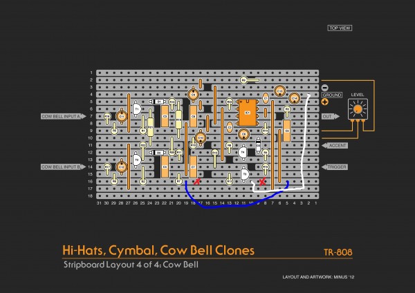
I have 'successfully' made the voice board, cymbal, hi-hats and cowbell.
Minus if you are out there still. Do you have the schematic for the cowbell?
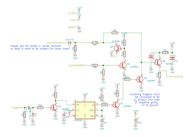
I have some strange behaviour. I can get a cowbell sound but not be triggering from the correct node.
It sounds great actually, I have used the specified 1.85ms and 1.25ms tuning and it sounds almost exactly like an original 808.
I was using a 5v connection and momentary push switch, but have now switched to 9V battery for testing.
Essentially what I have. It won't sound from triggering at R15 or T3. However will sound from R4, R8, R13 or T4. In fact, I have now removed T3 completely from the circuit and I still get it to trigger from the wrong above-mentioned points. However, there is a very low-level signal leakage somewhere. I can just about hear the cowbell sound continuously. This was the case even before removing T3
So I'm curious comparing to the original schematic, the triggering circuit, T3 & T4 doesn't seem correct. Why is the T4 emitter and R12 on the same rail as R2, R6 & R7 and all heading off to the level pot? Shouldn't T4 emitter and R12 just be grounded?
Any help is gratefully received. |
|
|
Back to top
|
|
|
Late_to_the_party
Joined: Sep 24, 2017
Posts: 21
Location: London
|
|
|
Back to top
|
|
|
Late_to_the_party
Joined: Sep 24, 2017
Posts: 21
Location: London
|
| Posted: Tue Feb 13, 2018 4:10 pm Post subject:
|
|
|
Help Please...
I'm pulling my hair out and was hoping someone could check my working...
I stupidly didn't just copy lysergist's stripboard layout of the rimshot/clave as I was trying to learn how to use Fritzing, and potentially get a PCB fabricated.
However, as far as I can see my schematic matches the original 808 schematics,
which should mean my layout is fine, but for both sounds, I get metallic 'PINGS' rather than the appropriate Rimshot/clave noises.
I know its a big ask, but any chance someone could have a look at my fritzing file and see where I must have done something wrong?
https://www.dropbox.com/s/fgwoaetpe78z07i/808%20Rim%20Shot%20%3A%20Clave%20TL074%20PCB.fzz?dl=0
Thanks in advance. |
|
|
Back to top
|
|
|
elmegil
Joined: Mar 20, 2012
Posts: 2179
Location: Chicago
Audio files: 16
|
| Posted: Tue Feb 13, 2018 5:59 pm Post subject:
|
|
|
First thing that jumps out at me is that you can't power an op amp off of +5V and -12V.....
edit: but I see that you're calling +12V 5V for some reason so that's just confusing, not wrong  |
|
|
Back to top
|
|
|
elmegil
Joined: Mar 20, 2012
Posts: 2179
Location: Chicago
Audio files: 16
|
| Posted: Tue Feb 13, 2018 6:39 pm Post subject:
|
|
|
Why are C9 and C10 increased from 4.7nF to 100nF? I see your notation looks like that's deliberate....
Same with C13 & C14
All your diodes are 1N4001's which is atypical. Normally these would be signal diodes, so 1N914 or 1N4148.
Note that Q1 is a FET, not BJT. I know you've got the transistor noted there, but your symbol is for a BJT....
C6 has the dual notation, but "your" notation is 0pF?? Similarly for C5. Right value in parens, what's the "0pF"?
C3 is marked as .022pF but it should be .0022 just like C1 & C2.
I don't see a resistance value in the original for R324 (your R27), how did you arrive at 220K?
I suspect the most likely problems are the 100nF instead of basically 5nF caps, those will likely move the frequency of those bridged-T networks way down (20x!), and/or C3 having the wrong value. |
|
|
Back to top
|
|
|
Late_to_the_party
Joined: Sep 24, 2017
Posts: 21
Location: London
|
| Posted: Wed Feb 14, 2018 3:27 am Post subject:
|
|
|
Wow, thanks for the speedy reply. Sorry for the confusion, I should have tidied up the labelling and I should have said in my original post some of the teething problems I have run into with Fritzing.
For some reason, it wouldn't allow me to change the values on many of the components, so I used what was available and included the true value with the part number.
You're absolutely right
So yes +5V is +12. The diodes I'm using are 1N914. I couldn't find a JFET symbol.
The 0pF was just to force me to look at the parens.
Good spot I mis-labelled C3, but actually used a 0.0022 in the circuit.
The 100nF caps are all 4700pF as the original.
I think I got the value of R324 from lysergist layout. Would changing this value affect the tuning?
Thanks again for running your keen eye over this and sorry for the confusing labelling, I'm just getting to grips with Fritzing. But all values are as original except the R324 220K guess. So I'm still scratching my head with this!
Hahahah argh |
|
|
Back to top
|
|
|
Late_to_the_party
Joined: Sep 24, 2017
Posts: 21
Location: London
|
| Posted: Wed Feb 14, 2018 3:37 am Post subject:
|
|
|
Things I should also mention.
My pot doesn't affect the level at all?
I am powering this from +-15V
and accent is tied to +15 could this be overdriving the circuit too much? |
|
|
Back to top
|
|
|
elmegil
Joined: Mar 20, 2012
Posts: 2179
Location: Chicago
Audio files: 16
|
| Posted: Wed Feb 14, 2018 6:44 am Post subject:
|
|
|
Accent at 15V is maybe a bit high. Spec is 4V to 14V.
But it looks like you have a Euro connector, are you not connecting to +/- 12V?
I suppose as a percentage of Vcc that still puts accent pretty high, you might try putting an additional 1 or 2K between VCC and the junction of R35 and Q5.
I did *not* look over your stripboard, BTW, to ensure it was right. I have found that stripboard work can be a lot more problematic to troubleshoot than other things, so....
Maybe wire a 1M pot in for that R324 thing and if changing the value there changes your circuit's behavior?
Otherwise my main guess is that metallic pings are definitely a sign of too *high* a frequency, so I'd guess there's either a short in one of the bridged T's or else an incorrect resistor value (which in the symmetry of this thing is more likely than an incorrect cap). |
|
|
Back to top
|
|
|
Late_to_the_party
Joined: Sep 24, 2017
Posts: 21
Location: London
|
| Posted: Wed Feb 14, 2018 6:50 am Post subject:
|
|
|
Thanks so much.
I know what you mean about Stripboard being problematic to troubleshoot. I've been going over it for the last 2 weeks trying to find the error, and still no luck.
I put a 2.3M resistor before accent top reduce it to 12.5V and it had no effect.
Greta idea about the 1M pot. I'll see what it does.
And I'll check again for shorts, wrong cap/resitors.
Cheers man.
In the meantime I'm just soldering lysergist's layout to compare.
many thanks |
|
|
Back to top
|
|
|
Late_to_the_party
Joined: Sep 24, 2017
Posts: 21
Location: London
|
| Posted: Wed Feb 14, 2018 7:13 am Post subject:
|
|
|
Oh and yes.
I decided to use eurorack connectors, but my power supply is variable 12-15v. FC Routemaster by Rick Holt. so I decided to leave it at 15V as the Original 808n PS. |
|
|
Back to top
|
|
|
Late_to_the_party
Joined: Sep 24, 2017
Posts: 21
Location: London
|
| Posted: Wed Feb 21, 2018 4:28 pm Post subject:
|
|
|
Sooooo I've been bashing my head against the wall and tearing my hair out of the rimshot.
I've checked over everything a million times.
I can't see a single fault. Just as I was about to throw it in the bin.
I noticed it actually makes a rimshot sound when I turn the power supply off.
I don't have the mental skills to analyse this behaviour to diagnose the problem, but I'm sure there's someone out there clever than me who can help...
My thoughts were it could be transistor related.
Does this, power off = make the right noise mean I have one specific Transistor back to front? Are all my resistors back to front?
Had anyone had experience with this before who can shed some light?
Many thanks in advance. |
|
|
Back to top
|
|
|
Late_to_the_party
Joined: Sep 24, 2017
Posts: 21
Location: London
|
| Posted: Fri Feb 23, 2018 10:51 am Post subject:
|
|
|
Update,
Currently working to get my version of the layout working, as per the link to my Fritzing file.
I can now get to trigger the sounds but from the wrong place.
Applying a voltage to any resistor connected to the base of Q60 will trigger the sounds. They sound authentic but have a large amount of hum/noise with them. The hum is only present when triggering so the muting circuit is working.
I have made a little high pass filter to make it more acceptable but the hum is still present. But I'd much prefer for it to not need the high pass filter, it cuts out important frequencies from the rimshot.
And I can't get my head around why this won't trigger from R297?
Please help.
Last edited by Late_to_the_party on Fri Feb 23, 2018 11:04 am; edited 1 time in total |
|
|
Back to top
|
|
|
Late_to_the_party
Joined: Sep 24, 2017
Posts: 21
Location: London
|
| Posted: Fri Feb 23, 2018 10:52 am Post subject:
|
|
|
note:
I have changed all my transistors from BC546/BC556 to BC549/BC559 as i thought the low noise versions might solve the hum but no luck.
And the VR16 100kA still does not affect the level? |
|
|
Back to top
|
|
|
lysergist
Joined: Jan 14, 2016
Posts: 36
Location: France
Audio files: 2
|
| Posted: Sat Mar 24, 2018 7:33 am Post subject:
|
|
|
| Hi Apollo, do you still have issues with your rimshot circuit ? Mine works perfectly, the diagram has been verified but maybe i should check again. If you had a rimshot sound while turning the power on/off, i guess you should have a trigger problem. (Also if you have a multimeter check if you have +12/15V at pin 4 and -12/15V pin 11). While testing you should tie the accent point to +15V to hear it at full level. |
|
|
Back to top
|
|
|
Late_to_the_party
Joined: Sep 24, 2017
Posts: 21
Location: London
|
| Posted: Sat Mar 24, 2018 7:56 am Post subject:
|
|
|
Hi lysergist, thanks for getting back to me.
Rimshot and clave working beautifully thanks. After some tinkering with the tracks (double checking for shorts) then replacing all the transistors again it now triggers from the right place.
I also discovered one source for humming with my set up. I have a Universal Audio Apollo, audio interface which I test my stripboards on. Just plug the output jack into an input and listen in headphones. It can be used in stand-alone mode without being connected to my laptop. However, if it is used in this manner, it seems it isn't grounded. Once I connected it to my laptop via thunderbolt... Problem solved.
In other news, I have made layouts for the Tom/Congas. the High and Low are verified working. I still need to troubleshoot the Mid Tom.
I will post layouts of these soon. But I designed them in Fritzing and it a pig for anyone to actually read the layout and the components have a 2.5D isometric view. This means tightly place components overlay each other and you can't see exactly where the leads go.
I am working on transferring them to a better layout software. I have downloaded 'DIY Layout".
Are there any other go freeware/donationware/cheapware options for osx.
The reason I liked fritzing is it creates a schematic and you make the stripboard layout.
The schematic can then be verified against the service manual. Are there any other layout software programs that do this?
Today I will be making your Clap, it is the one I've been looking forward to the most. Saved the best for last. |
|
|
Back to top
|
|
|
helix_modular
Joined: Aug 31, 2017
Posts: 27
Location: Germany
|
| Posted: Mon Apr 16, 2018 1:11 pm Post subject:
Re: Cowbell |
|
|
| Apollo View wrote: | Ok, so I have possibly solved this myself, any feedback would really be appreciated.
I the solution hasn't stopped the slight signal leak, however, the output is now much louder, so my input gain to the soundcard is lower so the 'noise' is less noticeable.
I have made two cuts to isolate T3 and R12 from the Level pot path, added jumpers so R2, R6, R7 still go to the level pot. And added a jumper so T3's emitter and R12 now go to ground.
Hope this helps others in future. |
Hey folks,
I've spent quite a few hours debugging my cowbell as well. Yet it turned out, that the layout by -minus- was correct and it was my sheer carelessness. 
Therefore, I'm quite surprised Apollo had the problems as stated above -- in fact, the level pot has one leg tied to ground, so... nothing wrong with that. 
Anyway, the BOM has two minor mistakes:
1) the level pot should be 5kA (not 100k). Doesn't do much, but feels more 'natural'.
2) C5 (Roland schematic: C76) should be 22n (not 2n2). Again, this does not affect the sound very noticeably, but for the sake of completeness...
Cheers |
|
|
Back to top
|
|
|
brunob
Joined: Apr 16, 2018
Posts: 1
Location: Paris, France.
|
| Posted: Wed Apr 18, 2018 6:00 am Post subject:
|
|
|
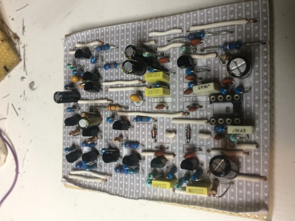
Hello everybody,
first off, thanks to all the contributors here, this board is awesome!
I'm fairly new to all this, and I just wanted to share a bit of my experience.
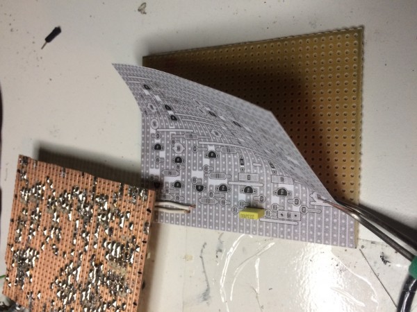
I don't know if this is obvious or not, I just didn't see this trick any where yet so I thought I could share..
After a first attempt, I found it very tedious to count the rows and columns on the board to find the right components place..
So I printed a 1/1 scale copy of the layout and sticked it directly on the stripboard: pinning the components in the right spot just got so easy!
The hihat is mostly working, I just still have a small volume problem, it might be a bad pot.
Thanks -minus-!
Cheers,
bruno
| Description: |
|
| Filesize: |
1.76 MB |
| Viewed: |
624 Time(s) |
| This image has been reduced to fit the page. Click on it to enlarge. |
|
| Description: |
|
| Filesize: |
1.58 MB |
| Viewed: |
653 Time(s) |
| This image has been reduced to fit the page. Click on it to enlarge. |
|
_________________
http://cmosorchestra.com |
|
|
Back to top
|
|
|
RyBowk
Joined: Nov 25, 2018
Posts: 33
Location: England
|
Posted: Fri Nov 30, 2018 3:52 am Post subject:
808 layout
Subject description: Complete |
|
|
I would like to give a massive thanks to minus who shared these layouts many moons ago.
I have just completed the sound board and the cowbell, both worked first time without any problems which is a testament to the planning and completeness of these layouts.
Thank you thank you 🙏 |
|
|
Back to top
|
|
|
RyBowk
Joined: Nov 25, 2018
Posts: 33
Location: England
|
| Posted: Fri Nov 30, 2018 3:55 am Post subject:
|
|
|
| brunob wrote: | Hello everybody,
first off, thanks to all the contributors here, this board is awesome!
I'm fairly new to all this, and I just wanted to share a bit of my experience.
I don't know if this is obvious or not, I just didn't see this trick any where yet so I thought I could share..
After a first attempt, I found it very tedious to count the rows and columns on the board to find the right components place..
So I printed a 1/1 scale copy of the layout and sticked it directly on the stripboard: pinning the components in the right spot just got so easy!
The hihat is mostly working, I just still have a small volume problem, it might be a bad pot.
Thanks -minus-!
bruno |
This is a great idea |
|
|
Back to top
|
|
|
RyBowk
Joined: Nov 25, 2018
Posts: 33
Location: England
|
| Posted: Wed Jan 02, 2019 3:34 pm Post subject:
|
|
|
| lysergist wrote: | Ok i finished the clap ! Sounds really nice to me. All transistors are BC547/557, i used 2CS945 and 2SA733, but there's no difference in the sound. I used cheap BA6110 i've found on ebay, and they work properly !
Maybe i'll make another version with the CA3080, but a NPN/PNP buffer needs to be added. I have also added two mods, replace R376 (47K) by a 100k pot to control the noise reverb amount, and replace the trimmer by a 10k potentiometer. |
Hi there, please excuse my dumbness but are selectors 1, 2 & 3 connected to a switch? Also what source does the white noise in come from?
Many thanks for your help and patience, Ryan |
|
|
Back to top
|
|
|
helix_modular
Joined: Aug 31, 2017
Posts: 27
Location: Germany
|
Posted: Mon Feb 11, 2019 1:38 pm Post subject:
TR-808 Tom/Conga
Subject description: Stripboard |
|
|
A bit late for the party, but here are my stripboard layouts for
Low Tom/Conga
Mid Tom/Conga
High Tom/Conga
All layouts are based on the mid tom (basically it is the same circuit, but some terminals are not used for low and high). I have not build the low tom this way, since I had a 'proper' PCB for this one. Mid and High are tested (working) and sounding about right.
The designators for the components comply with the Roland service manual for the TR-808. I have included the noise source on each board, but it may be shared (as in the original design).
Please refer to the service manual for wiring up pots and jacks. Do not forget the hookup wires for +15V and -15V (red and green pads respectively). Print the pdf on DIN A4 paper with 1:1 scaling for easy transfer.
Enjoy!
| Description: |
|

Download (listen) |
| Filename: |
TR-808_HighTomConga.pdf |
| Filesize: |
146.78 KB |
| Downloaded: |
787 Time(s) |
| Description: |
|
Download (listen) |
| Filename: |
TR-808_MidTomConga.pdf |
| Filesize: |
142.15 KB |
| Downloaded: |
682 Time(s) |
| Description: |
|
Download (listen) |
| Filename: |
TR-808_LowTomConga.pdf |
| Filesize: |
146.71 KB |
| Downloaded: |
675 Time(s) |
|
|
|
Back to top
|
|
|
|

 Forum index » DIY Hardware and Software