| Author |
Message |
mosc
Site Admin

Joined: Jan 31, 2003
Posts: 18240
Location: Durham, NC
Audio files: 224
G2 patch files: 60
|
 Posted: Mon Feb 11, 2008 11:17 am Post subject:
Power supplies Posted: Mon Feb 11, 2008 11:17 am Post subject:
Power supplies |
  |
|
Most CMOS logic will work well on 5 Volt DC supplies. Before starting to build a Lunetta, it's a good idea to start with a good 5V DC supply.
This topic is for people to post designs for such supplies, or places where they can be obtained, etc.
CMOS logic uses very low power, so it is possible to use batteries. Standard AAA, AA, D, and C cells are about 1.5 V. So 3 or 4 in series makes a usable supply and your Lunetta becomes portable.
Please post power supply designs here, as well as questions and comments.
_________________
--Howard
my music and other stuff |
|
|
Back to top
|
|
 |
Clack

Joined: Aug 08, 2005
Posts: 438
Location: Walthamstow - london
Audio files: 5
G2 patch files: 1
|
| Posted: Mon Feb 11, 2008 1:44 pm Post subject:
|
|
|
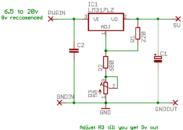
I just based this off the lm317 datasheet and other sources I could find cos its quick to lay out - and i know how to do it!  . .
Based on the LM317 - PSU2 version is probably better - all resistors in ohms not Kohms
6.5-20v dc needed
| Description: |
|
| Filesize: |
6.32 KB |
| Viewed: |
516 Time(s) |
| This image has been reduced to fit the page. Click on it to enlarge. |

|
| Description: |
|
| Filesize: |
8.28 KB |
| Viewed: |
505 Time(s) |
| This image has been reduced to fit the page. Click on it to enlarge. |
|
_________________
Clacktronics.co.uk |
|
|
Back to top
|
|
|
blue hell
Site Admin

Joined: Apr 03, 2004
Posts: 24419
Location: The Netherlands, Enschede
Audio files: 297
G2 patch files: 320
|
| Posted: Mon Feb 11, 2008 2:05 pm Post subject:
|
|
|
I'd not use the adjustable one ... even bad old TTL is happy from 4.75 to 5.25 V , so it's not too critical.
_________________
Jan
also .. could someone please turn down the thermostat a bit.
 |
|
|
Back to top
|
|
|
Clack
Joined: Aug 08, 2005
Posts: 438
Location: Walthamstow - london
Audio files: 5
G2 patch files: 1
|
| Posted: Mon Feb 11, 2008 2:20 pm Post subject:
|
|
|
oh right ok.. cool. Bit over the top then! to be honest they dont really need schematics there is barely any parts - I guess a little PCB/Stripboard layout is all that is needed
_________________
Clacktronics.co.uk |
|
|
Back to top
|
|
|
williamsharkey

Joined: Jul 31, 2005
Posts: 61
Location: usa
|
| Posted: Tue Feb 12, 2008 9:00 am Post subject:
|
|
|
<- newbie
Why regulate voltage when one can combine household batteries in series and parallel to obtain ~5 volts.
Is this for people who: don't want to use batteries and have a dc power supply in the range of 6.5 to 20 volts? |
|
|
Back to top
|
|
|
Clack
Joined: Aug 08, 2005
Posts: 438
Location: Walthamstow - london
Audio files: 5
G2 patch files: 1
|
| Posted: Tue Feb 12, 2008 9:10 am Post subject:
|
|
|
Yeah, it works with most dc wall warts ( you find them everywhere theese days - it will work with most ) - its especially usefull if you want some LED's. too many of them an it will not take long to drain battery power. Batteries wont need regulators
Im not a great fan of batteries when you use them in your bedroom - it seems a waste - although im sure you could say using mains is a waste too.
As blue hell said though - using this regulator is probably a bit over the top - i'll leave it up anyway. but a lm7805 is probably better - they are easy to find sometimes in electronic junk too.
_________________
Clacktronics.co.uk |
|
|
Back to top
|
|
|
blue hell
Site Admin
Joined: Apr 03, 2004
Posts: 24419
Location: The Netherlands, Enschede
Audio files: 297
G2 patch files: 320
|
| Posted: Tue Feb 12, 2008 10:04 am Post subject:
|
|
|
| Mr Clack wrote: | | As blue hell said though - using this regulator is probably a bit over the top |
Didn't mean to say that .. did mean to say that the adjustable one (the one with the trimmer) would be over the top
_________________
Jan
also .. could someone please turn down the thermostat a bit.
|
|
|
Back to top
|
|
|
Clack
Joined: Aug 08, 2005
Posts: 438
Location: Walthamstow - london
Audio files: 5
G2 patch files: 1
|
| Posted: Tue Feb 12, 2008 12:02 pm Post subject:
|
|
|
oh right, heh - I just put that on because 680R is the nearest value I can get
_________________
Clacktronics.co.uk |
|
|
Back to top
|
|
|
williamsharkey
Joined: Jul 31, 2005
Posts: 61
Location: usa
|
| Posted: Tue Feb 19, 2008 11:18 am Post subject:
|
|
|
Why is C2 drawn differently than C1, do they represent different types of capacitors?
Perhaps the order of connection of the leads matters in C1? |
|
|
Back to top
|
|
|
23isgood

Joined: Nov 18, 2006
Posts: 236
Location: San Francisco, CA bay area
Audio files: 13
|
|
|
Back to top
|
|
|
danielwarner
Joined: Dec 18, 2006
Posts: 65
Location: Sacramento
|
| Posted: Tue Feb 19, 2008 4:48 pm Post subject:
|
|
|
| williamsharkey wrote: | Why is C2 drawn differently than C1, do they represent different types of capacitors?
Perhaps the order of connection of the leads matters in C1? |
C1 is a polarized capacitor, e.g. an electrolytic or tantalum, which will most likely have a stripe with a "-" symbol indicating the negative lead. It must be oriented correctly, or at best will not work and at worst will explode. I've seen capacitors explode, it's amusing but dangerous! The funny thing is it was in a class at school where we were accidentally given electrolytics rated at a lower voltage than the power supply for the circuit. When the first cap popped, we all assumed they'd oriented their cap incorrectly. Then mine blew up and somebody checked the voltage rating and it was not up to par. Blame the lab tech  . Anyway for the rest of the semester we always checked the voltage ratings on the caps! . Anyway for the rest of the semester we always checked the voltage ratings on the caps!
Any capacitor rated at a higher voltage than the wall wart you're using should be fine. For instance with a 12VDC wall wart, a 16V capacitor will be fine. |
|
|
Back to top
|
|
|
williamsharkey
Joined: Jul 31, 2005
Posts: 61
Location: usa
|
| Posted: Tue Feb 19, 2008 7:38 pm Post subject:
|
|
|
| Quote: | | Any capacitor rated at a higher voltage than the wall wart you're using should be fine. For instance with a 12VDC wall wart, a 16V capacitor will be fine. |
What if you have two 10V capacitors. If you place them in parallel, I wonder if they can handle more than their individual ratings?
(I know not to do any sort of experimenting with power supplies, so you can answer the following question unhindered by safety concerns ) |
|
|
Back to top
|
|
|
danielwarner
Joined: Dec 18, 2006
Posts: 65
Location: Sacramento
|
| Posted: Tue Feb 19, 2008 9:06 pm Post subject:
|
|
|
| In this instance, the cap comes after the voltage regulator, after the voltage has been regulated down to +5V. You'll be fine with a 10V cap. |
|
|
Back to top
|
|
|
danielwarner
Joined: Dec 18, 2006
Posts: 65
Location: Sacramento
|
| Posted: Fri Feb 22, 2008 3:04 am Post subject:
|
|
|
For future reference:
If you have two 10V caps, you can put them in series and they will behave like one 20V cap at HALF the farad rating
Two 10V 20uF caps in series would give you a 20V 10uF cap |
|
|
Back to top
|
|
|
|

 Forum index » DIY Hardware and Software » Lunettas - circuits inspired by Stanley Lunetta
