| Author |
Message |
TekniK

Joined: Aug 10, 2008
Posts: 1059
|
 Posted: Thu Feb 24, 2011 1:13 pm Post subject: Posted: Thu Feb 24, 2011 1:13 pm Post subject:
|
  |
|
Damn,thats awesome,congratulations !
It realy asks to be touched,nice design |
|
|
Back to top
|
|
 |
loydb
Joined: Feb 04, 2010
Posts: 393
Location: Providence, RI
|
| Posted: Thu Feb 24, 2011 6:09 pm Post subject:
|
|
|
| jordroid wrote: | Here are some other recent things. There is an MFOS 16 step sequencer, sound lab mini-synth + and an MFOS phaser on one big panel.
|
I love it.
| jordroid wrote: |
-a module for bringing guitars or other instruments up to synth level, providing boosted clean signal out, squared out and octave down squared out along with gate and trigger signals, based on the MFOS sub commander mostly
|
Do you have a pcb and/or scheme for this that you'd share? Thanks!
_________________
MFOS Ultimate Expand-o-tron Build Log: http://www.electro-music.com/forum/post-308797.html#308797
MFOS Mini-Controller Build Log [FINISHED!]: http://www.electro-music.com/forum/topic-42968.html |
|
|
Back to top
|
|
|
jordroid
Joined: Jan 17, 2010
Posts: 193
Location: ithaca, new york
|
| Posted: Sat Feb 26, 2011 3:06 pm Post subject:
|
|
|
[quote="loydb"
Do you have a pcb and/or scheme for this that you'd share? Thanks![/quote]
Well, i did it in my usual disorganized way by breadboarding Ray's circuit and then tweaking it till i liked it, and then transfering the breadboarded circuit straight to perfboard without taking proper notes.  When i say based on Ray's design i mean it's mostly his exactly, with just a few changes. When i say based on Ray's design i mean it's mostly his exactly, with just a few changes.
If i remember correctly i added a gain potentiometer to the front and a comparator wired to light up an led when the input signal was right around +/- 5 volts so i would have a visual indication of when the signal was at the desired level.
I also messed with the values around the gate circuit to get it to trigger reliably with my guitar, i never became super happy with it, mostly because i have a hard time playing consistently enough, not because of circuit deficiencies.
As is the levels of the pulse and sub pulse were a bit lower than +/- 5 volts, i don't remember if i did anything about that or not, i know i thought about it. Changing R48 and R49 (from the sub commander schematic) should alter the level of the pulse and sub pulse if desired. As a stand alone guitar effect it's probably not necessary but i wanted it to interface nicely with modular gear.
I used the opamp calculators and comparator calculator on Ray's site a bunch, and then just breadboarded to taste. I will add that i am fairly new to this and don't know if what i've done is anywhere near "best practice", or closer to "design nightmare", but if you want anything more specific i could pretty easily pull that module out and try to figure out exactly what i did.  |
|
|
Back to top
|
|
|
droffset

Joined: Feb 02, 2009
Posts: 515
Location: London area
Audio files: 2
|
|
|
Back to top
|
|
|
TekniK
Joined: Aug 10, 2008
Posts: 1059
|
| Posted: Sun Feb 27, 2011 3:06 am Post subject:
|
|
|
| droffset wrote: | Here's something I made for that 555 design contest. It was really fun to make and I learned a lot on the fly while doing it.
|
haha,awesome thing |
|
|
Back to top
|
|
|
iorobyy

Joined: Sep 26, 2005
Posts: 65
Location: Italy
|
|
|
Back to top
|
|
|
loydb
Joined: Feb 04, 2010
Posts: 393
Location: Providence, RI
|
|
|
Back to top
|
|
|
TekniK
Joined: Aug 10, 2008
Posts: 1059
|
| Posted: Sun Feb 27, 2011 12:23 pm Post subject:
|
|
|
| wow very nice those arp panels |
|
|
Back to top
|
|
|
dougseidel

Joined: Feb 10, 2010
Posts: 74
Location: NJ
|
|
|
Back to top
|
|
|
TekniK
Joined: Aug 10, 2008
Posts: 1059
|
| Posted: Mon Feb 28, 2011 10:49 am Post subject:
|
|
|
i like the dual lfo look  |
|
|
Back to top
|
|
|
jordroid
Joined: Jan 17, 2010
Posts: 193
Location: ithaca, new york
|
| Posted: Mon Feb 28, 2011 2:47 pm Post subject:
|
|
|
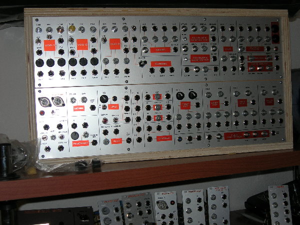
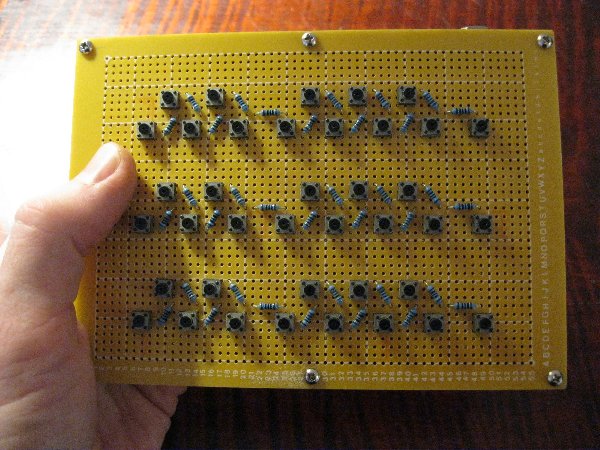
Here is a "just for fun" project. My brother gave me a literal bucket full of tiny momentary switches someone was tossing out, and i wanted to do something with them. It's a 3 octave single buss keyboard using Ray Wilson's design. The lowest octave is the bottom row, highest on top, with the two middle "C" notes appearing twice. Inside the box is just the switch/100r resistor part, it connects to the "brain" part with a TRS 1/4" cable. Ultimately i want to use it in a pre patched synth with an Acoupel CV recorder/sequencer as a remote control for programming sequences, and for directly playing in a twitchy/video game button mashing kind of way. I was a little bit worried that it would have issues with glitchy triggering, but it works great!
| Description: |
|
| Filesize: |
1004.57 KB |
| Viewed: |
233 Time(s) |
| This image has been reduced to fit the page. Click on it to enlarge. |
|
| Description: |
|
| Filesize: |
1.5 MB |
| Viewed: |
243 Time(s) |
| This image has been reduced to fit the page. Click on it to enlarge. |
|
|
|
|
Back to top
|
|
|
adambee7
Joined: Apr 04, 2009
Posts: 420
Location: united kingdom
|
| Posted: Mon Feb 28, 2011 2:53 pm Post subject:
|
|
|
| that would be great to add to a sequencer aswell. |
|
|
Back to top
|
|
|
Boogdish
Joined: Sep 21, 2009
Posts: 122
Location: Bloomington, IN
|
| Posted: Wed Mar 02, 2011 7:49 am Post subject:
|
|
|
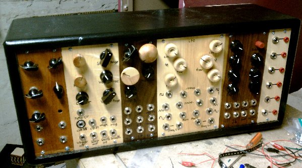
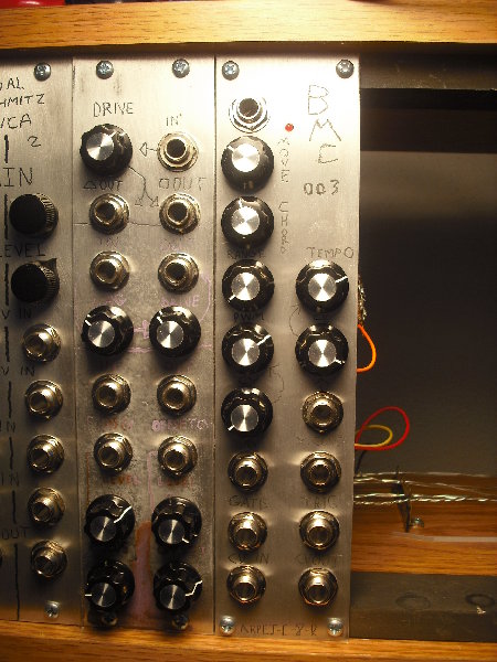
My arpeggiator prototype. Controls are (left to right, from top left):
-Reset (goes to root note and restarts clock)
-Movement (Up/down, up repeating, down repeating, pendulum, up non-repeating, down non-repeating, random)
-Chord to arpeggiate(Major, Minor, Major 7, Minor 7, Maj 7 w/o 5th, Min 7 w/o 5, 1 + 5, Octaves)
-Range (Selects between 1 and 5 octaves)
-Tempo
-PWM for the gate out
-Tempo modulator attenuator
-PWM modulator attenuator
-Tempo mod in
-PWM mod in
-Gate out
-Trigger out
-CV in
-CV out
| Description: |
|
| Filesize: |
1.04 MB |
| Viewed: |
212 Time(s) |
| This image has been reduced to fit the page. Click on it to enlarge. |
|
|
|
|
Back to top
|
|
|
dougseidel
Joined: Feb 10, 2010
Posts: 74
Location: NJ
|
| Posted: Wed Mar 02, 2011 8:09 am Post subject:
|
|
|
| Boogdish: I like the labels on this- do you etch right into those panels? |
|
|
Back to top
|
|
|
emdot_ambient
Joined: Nov 22, 2009
Posts: 667
Location: Frederick, MD
|
| Posted: Wed Mar 02, 2011 8:11 am Post subject:
|
|
|
| Boogdish wrote: | My arpeggiator prototype. Controls are (left to right, from top left):
-Reset (goes to root note and restarts clock)
-Movement (Up/down, up repeating, down repeating, pendulum, up non-repeating, down non-repeating, random)
-Chord to arpeggiate(Major, Minor, Major 7, Minor 7, Maj 7 w/o 5th, Min 7 w/o 5, 1 + 5, Octaves)
-Range (Selects between 1 and 5 octaves)
-Tempo
-PWM for the gate out
-Tempo modulator attenuator
-PWM modulator attenuator
-Tempo mod in
-PWM mod in
-Gate out
-Trigger out
-CV in
-CV out |
COOL! I'm looking forward to this one!
_________________
Looking for a certain ratio since 1978 |
|
|
Back to top
|
|
|
kupfer_m
Joined: Oct 14, 2010
Posts: 48
Location: Belgium
|
| Posted: Sun Mar 06, 2011 12:12 pm Post subject:
|
|
|
The first of many....
Yusynth VCO
 |
|
|
Back to top
|
|
|
Boogdish
Joined: Sep 21, 2009
Posts: 122
Location: Bloomington, IN
|
|
|
Back to top
|
|
|
mark_olson
Joined: Oct 26, 2006
Posts: 177
Location: Lawrence, Kansas
|
| Posted: Mon Mar 07, 2011 8:49 am Post subject:
|
|
|
Boogdish:
Your front panels are absolutely fantastic. How are you doing the lettering?
Really really nice!
I don't have the means or even the desire to make panels that are really "pretty", mine have a decidedly DIY look, but I wish I could make ones that really have balls like yours do.
Mark
Last edited by mark_olson on Mon Mar 07, 2011 1:23 pm; edited 1 time in total |
|
|
Back to top
|
|
|
TekniK
Joined: Aug 10, 2008
Posts: 1059
|
| Posted: Mon Mar 07, 2011 12:58 pm Post subject:
|
|
|
| kupfer_m wrote: | The first of many....
Yusynth VCO
|
neat,nice! |
|
|
Back to top
|
|
|
Photon

Joined: Mar 22, 2005
Posts: 363
Location: Boston
Audio files: 1
|
| Posted: Mon Mar 07, 2011 1:09 pm Post subject:
|
|
|
| an electric engraver maybe? anyway it looks cool. |
|
|
Back to top
|
|
|
Boogdish
Joined: Sep 21, 2009
Posts: 122
Location: Bloomington, IN
|
| Posted: Mon Mar 07, 2011 3:13 pm Post subject:
|
|
|
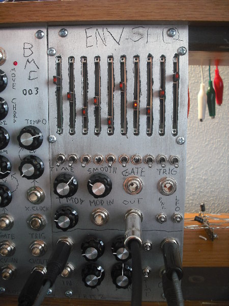
Oh, I meant to respond to Doug's comment in that last post but forgot. Thanks for the kind words, gents.
I engrave with a dremel, then spray paint black and sand off the excess spray paint, which also shines up the rest of the surface a bit. I'm still working on my engraving technique, I wish I had more control than I do now.
Also, I made a little video showing the ENV-SEQ. I apologize in advance for my crap camera work.
http://www.youtube.com/watch?v=mKvlIneAobA |
|
|
Back to top
|
|
|
mark_olson
Joined: Oct 26, 2006
Posts: 177
Location: Lawrence, Kansas
|
| Posted: Mon Mar 07, 2011 3:44 pm Post subject:
|
|
|
| Boogdish wrote: | | ...wish I had more control... |
Yeah, I hear that but I think it's the lack of control that makes them look so cool, and that will be hard to fake if you acquire more "skill". |
|
|
Back to top
|
|
|
jordroid
Joined: Jan 17, 2010
Posts: 193
Location: ithaca, new york
|
| Posted: Mon Mar 07, 2011 6:06 pm Post subject:
|
|
|
| Boogdish, super cool envelope rig, i was thinking it was a 4017 sequencer (10 steps and all) except the forward/backward capability makes me think it's not, is it done with a pic, or...? Cool idea! |
|
|
Back to top
|
|
|
Boogdish
Joined: Sep 21, 2009
Posts: 122
Location: Bloomington, IN
|
| Posted: Tue Mar 08, 2011 2:16 pm Post subject:
|
|
|
It's two chips, a 16F913 PIC and a quad op amp being used as an output buffer and voltage summer/limiter of the time CV. I'm sure it could be done using standard CMOS chips, but for me, it's easier to figure it out with a PIC.
I'm thinking about starting over with it and have the PIC read the values of the pots then output with the PWM or a standalone DAC. That way the PIC could do the filtering of between step voltages and have smoother transitions. I think I'd also have try having separate time controls for A/S/R. |
|
|
Back to top
|
|
|
emdot_ambient
Joined: Nov 22, 2009
Posts: 667
Location: Frederick, MD
|
|
|
Back to top
|
|
|
|

 Forum index » DIY Hardware and Software