| Author |
Message |
alkopop79
Joined: Aug 21, 2008
Posts: 52
Location: London
|
|
|
Back to top
|
|
 |
elmegil

Joined: Mar 20, 2012
Posts: 2179
Location: Chicago
Audio files: 16
|
 Posted: Sat Apr 13, 2013 6:27 am Post subject: Posted: Sat Apr 13, 2013 6:27 am Post subject:
|
  |
|
Have you checked to see if the chip is bad, by putting in another one?
TL072 does not operate single supply. LM324 does, but it's a quad chip. I believe LM321 would be the single amp version, but I've not used them. |
|
|
Back to top
|
|
|
blue hell
Site Admin

Joined: Apr 03, 2004
Posts: 24396
Location: The Netherlands, Enschede
Audio files: 296
G2 patch files: 320
|
| Posted: Sat Apr 13, 2013 6:33 am Post subject:
|
|
|
 alkopop79 alkopop79
The speaker ... I'd not directly drive a speaker from an opamp .. if you want a speaker in the box make a separate power amp for it.
_________________
Jan
also .. could someone please turn down the thermostat a bit.
 |
|
|
Back to top
|
|
|
JovianPyx

Joined: Nov 20, 2007
Posts: 1988
Location: West Red Spot, Jupiter
Audio files: 224
|
| Posted: Sat Apr 13, 2013 8:15 am Post subject:
|
|
|
As Blue Hell said - the speaker - it's a very low impedance load and could easily cause the problem. As Blue suggests, better to run the speaker from a separate amplifier.
_________________
FPGA, dsPIC and Fatman Synth Stuff
Time flies like a banana.
Fruit flies when you're having fun.
BTW, Do these genes make my ass look fat?
corruptio optimi pessima
|
|
|
Back to top
|
|
|
richardc64

Joined: Jun 01, 2006
Posts: 679
Location: NYC
Audio files: 26
|
| Posted: Sat Apr 13, 2013 8:56 am Post subject:
|
|
|
It still wouldn't work.
For single supply, almost any op amp would work in this circuit IF the (+) input is biased to 1/2V+. (Which some mistakenly call a virtual ground.) Triggers should then be capacitor-coupled in.
_________________
Revenge is a dish best served with a fork... to the eye |
|
|
Back to top
|
|
|
JovianPyx
Joined: Nov 20, 2007
Posts: 1988
Location: West Red Spot, Jupiter
Audio files: 224
|
| Posted: Sat Apr 13, 2013 9:21 am Post subject:
|
|
|
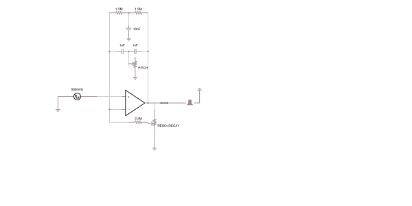
It's possible that the signal generator symbol might be intended to account for the required bias. I can't really tell for the symbol in the circle.
However, the signal generator also indicates 500 mHz which is .5 Hz. I suppose that this filter is intended to operate at very low frequencies?
_________________
FPGA, dsPIC and Fatman Synth Stuff
Time flies like a banana.
Fruit flies when you're having fun.
BTW, Do these genes make my ass look fat?
corruptio optimi pessima
|
|
|
Back to top
|
|
|
Scott Stites
Janitor


Joined: Dec 23, 2005
Posts: 4127
Location: Mount Hope, KS USA
Audio files: 96
|
| Posted: Sat Apr 13, 2013 9:57 am Post subject:
|
|
|
| JovianPyx wrote: | It's possible that the signal generator symbol might be intended to account for the required bias. I can't really tell for the symbol in the circle.
However, the signal generator also indicates 500 mHz which is .5 Hz. I suppose that this filter is intended to operate at very low frequencies? |
Looks to me that the signal generator is there to provide input pulses at a 0.5 Hz rate (as an illustration, I guess, of what it takes to ring the thing).
Like mentioned before, if it's single supply, it would need an artificial ground (1/2 Vcc) and (again) drive the speaker from a second amplifier.
_________________
My Site |
|
|
Back to top
|
|
|
alkopop79
Joined: Aug 21, 2008
Posts: 52
Location: London
|
| Posted: Sat Apr 13, 2013 12:31 pm Post subject:
|
|
|
Thanks for all the replies! I did further simulation and indeed, without virtual ground it won't work. THe circuit can be found here:
https://www.circuitlab.com/circuit/g52648/twin-t-with-trigger/
You can open it in the editor and play with it. The time domain simulation will even draw a nice kick drum. Eventually I found a sail splitter circuit here:
http://tangentsoft.net/elec/bitmaps/vgrounds/rdiv.png
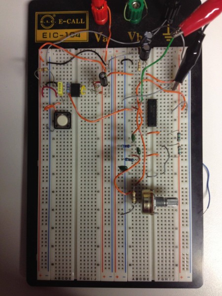
However, when I build the circuit on the breadboard, it doesn't work. With 9V DC supply instead of getting 4.5V, 0V and -4.5V I get 9V, 4.5V and 0V. It seems as if the caps weren't even in the circuit. I checked the polarity and the value of the caps and even used different ones. Still don't get any virtual ground, the circuit acts as a voltage divider. A photo of the breadboard circuit:
http://www.flickr.com/photos/alkopop79/8646491414/
It's beyond me why doesn't it work. Any ideas? |
|
|
Back to top
|
|
|
elmegil
Joined: Mar 20, 2012
Posts: 2179
Location: Chicago
Audio files: 16
|
| Posted: Sat Apr 13, 2013 12:46 pm Post subject:
|
|
|
| Are you using the "virtual ground" (yes I know I'm abusing the term) as your reference to see +/- 4.5V? If you're using "real ground" then what you describe is exactly what you would expect, yes? |
|
|
Back to top
|
|
|
alkopop79
Joined: Aug 21, 2008
Posts: 52
Location: London
|
| Posted: Sat Apr 13, 2013 1:13 pm Post subject:
|
|
|
| It's working. I was a dumbass: the ground of the multimeter has to go to the junction, the middle ground of the circuit. Indeed, from a 9V supply I get 4.5V, 0V and -4.5V. I changed the 741 to a TL072 and it works! So far I've only checked it with an oscilloscope and it very much looks like an analog drum! |
|
|
Back to top
|
|
|
alkopop79
Joined: Aug 21, 2008
Posts: 52
Location: London
|
| Posted: Sat Apr 13, 2013 1:13 pm Post subject:
|
|
|
| elmegil wrote: | | Are you using the "virtual ground" (yes I know I'm abusing the term) as your reference to see +/- 4.5V? If you're using "real ground" then what you describe is exactly what you would expect, yes? |
Erm, yes.  |
|
|
Back to top
|
|
|
elmegil
Joined: Mar 20, 2012
Posts: 2179
Location: Chicago
Audio files: 16
|
| Posted: Sat Apr 13, 2013 1:45 pm Post subject:
|
|
|
I've done even more foolish things and even owned up to them here, so don't feel too bad  |
|
|
Back to top
|
|
|
alkopop79
Joined: Aug 21, 2008
Posts: 52
Location: London
|
| Posted: Sat Apr 13, 2013 2:19 pm Post subject:
|
|
|
| Tried it with the amp but unfortunately it distorts the crap out of the signal. |
|
|
Back to top
|
|
|
alkopop79
Joined: Aug 21, 2008
Posts: 52
Location: London
|
| Posted: Sat Apr 13, 2013 2:20 pm Post subject:
|
|
|
| alkopop79 wrote: | | Tried it with the amp but unfortunately it distorts the crap out of the signal. |
Failed to mention, it's an LM386. |
|
|
Back to top
|
|
|
alkopop79
Joined: Aug 21, 2008
Posts: 52
Location: London
|
| Posted: Sat Apr 13, 2013 3:01 pm Post subject:
|
|
|
| Is it possible that the amp distorts because it gets -4.5V to 4.5V signal? It's a single supply amp though. |
|
|
Back to top
|
|
|
Scott Stites
Janitor
Joined: Dec 23, 2005
Posts: 4127
Location: Mount Hope, KS USA
Audio files: 96
|
| Posted: Sat Apr 13, 2013 5:28 pm Post subject:
|
|
|
| alkopop79 wrote: | | Is it possible that the amp distorts because it gets -4.5V to 4.5V signal? It's a single supply amp though. |
Well - I have yet to play with one of those buggers, but, according to the data sheet, it's a bit more than possible. Data sheet says absolute maximum input voltage is +/-0.4V.
Also, if you're powering the op amp from single supply, I think you will want to couple through a capacitor to the LM386 to get rid of any voltage offset.
_________________
My Site |
|
|
Back to top
|
|
|
Thomas_Henry
Joined: Jul 24, 2009
Posts: 170
Location: N. Mankato, MN
Audio files: 3
|
| Posted: Sat Apr 13, 2013 6:36 pm Post subject:
|
|
|
Hi Gang,
My suggestion would be to jettison the op-amp altogether and use a transistor as the gain element for the Twin-Tee. That's exactly what I did for the Sirius Metronome published in Nuts & Volts in January. I too used the 386 for the output stage. It all worked out quite nicely with a very satisfying woodblock sound.
http://www.nutsvolts.com/forums.html?/magazine/article/january2013_Henry
Click the mouse icon to preview the article.
Thomas Henry |
|
|
Back to top
|
|
|
alkopop79
Joined: Aug 21, 2008
Posts: 52
Location: London
|
| Posted: Sat Apr 13, 2013 8:11 pm Post subject:
|
|
|
| Thanks, neat circuit! I will give it a try! What's the difference between the LM380 and the LM386? |
|
|
Back to top
|
|
|
-minus-
Joined: Oct 26, 2008
Posts: 787
Audio files: 13
|
| Posted: Sat Apr 13, 2013 9:27 pm Post subject:
|
|
|
| Why is 'virtual ground' abusing the term? Can someone explain this? |
|
|
Back to top
|
|
|
elmegil
Joined: Mar 20, 2012
Posts: 2179
Location: Chicago
Audio files: 16
|
| Posted: Sat Apr 13, 2013 10:41 pm Post subject:
|
|
|
| I believe (though Richard can correct me if I misunderstood his comment) that it's because the true "virtual ground" is when you hold one of your op amp inputs at ground and it forces the other one to also be at ground potential even though they're not shorted. |
|
|
Back to top
|
|
|
Scott Stites
Janitor
Joined: Dec 23, 2005
Posts: 4127
Location: Mount Hope, KS USA
Audio files: 96
|
| Posted: Sun Apr 14, 2013 1:16 pm Post subject:
|
|
|
I actually decided to subscribe to N&V because I know TH has actually published a string of articles there.
_________________
My Site |
|
|
Back to top
|
|
|
alkopop79
Joined: Aug 21, 2008
Posts: 52
Location: London
|
|
|
Back to top
|
|
|
alkopop79
Joined: Aug 21, 2008
Posts: 52
Location: London
|
| Posted: Fri Apr 26, 2013 11:20 pm Post subject:
|
|
|
Friends,
the circuit works! It's pretty amazing, I get massive kicks on the output. However the circuit audibly 'buzzes' when I touch a pot. Also, the it tends to distort at higher frequencies and it's pretty noisy. Any ideas how to fix that?
https://soundcloud.com/alkopop79/twin-t-percussion-osc |
|
|
Back to top
|
|
|
sonic

Joined: Dec 02, 2010
Posts: 106
Location: Victoria BC
|
|
|
Back to top
|
|
|
elmegil
Joined: Mar 20, 2012
Posts: 2179
Location: Chicago
Audio files: 16
|
| Posted: Thu Aug 22, 2013 9:44 pm Post subject:
|
|
|
| I'm far away from anything to test with right now, but I'd expect the 3.3 to have more impact than the op amp. Do you have any 560k resistors? Put one in series and see if it improves anything, that should get you close to 3.8M.... |
|
|
Back to top
|
|
|
|

 Forum index » DIY Hardware and Software